Air is fed to the furnace through a jacket pre-heating the air, creating an insulation barrier and containing combustion gas leakages.
The air is introduced to the monolithic or brick refractory lined furnace space through a burner quarl.
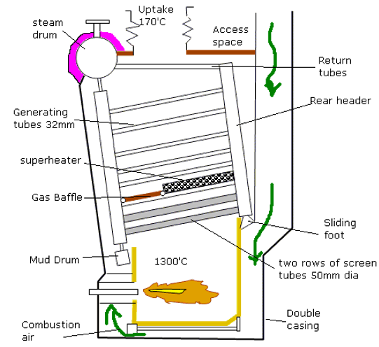
There is no water drum, but headers are connected to the steam drums via feeder and return tubes. A superheater is nested between the generating and screen tubes.
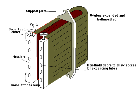
The design has the advantage of being easy to clean allowing the use of lower quality fuels. The disadvantage being that to get access to the headers for inspection of tube plugging requires a large number of handhole doors.
The drum is all welded and the casing bolted
In the early designs the drums were riveted or solid forged from a single ingot, but for modern boilers the drum is generally fabricated from steel plate of differing thicknesses and welded. The materials used are governed by classification society rules. Test pieces must be provided.
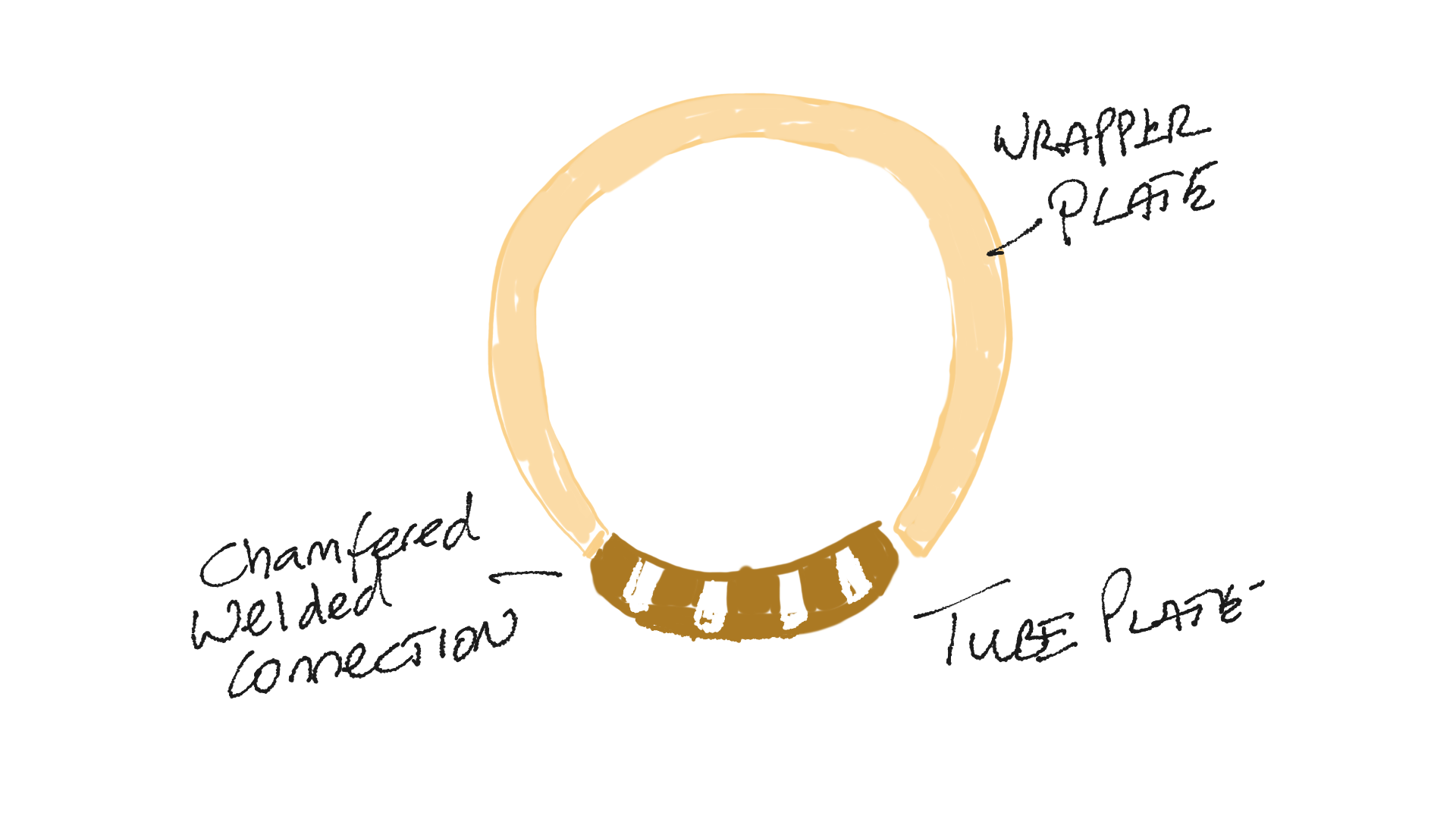
Cylindrical boiler drums are constructed from four plates. Two dished forged end plates, a thick wall tube plate ( thicker to accommodate the holes drilled in it without increased stress) and a thinner wrapper plate.
Note headers due to their smaller diameter may have flat end plates.
The wrapper and tube plate are rolled to the correct radius, descaled and then welded using an automated submerged arc process
Test pieces cut from the original material are attached to the construction in such a way that the longitudinal weld extends either side of the join. These pieces are later removed and shaped test shapes cut out from specified areas including across the weld.
The dished end pieces are accurately aligned and either automated or manually welded.
The longitudinal weld carries twice the stress of the circumferential weld.
Drum welds are x-ray non-destructive inspected. The test weld is cut into test pieces and subject to hardness, and strain testing.
After final machining is completed internal fixings , stub pieces and doublers are attached before the entire assembly is heat treated at 600 to 650'C.
The drum is hydrostatically pressure tested to class requirements.
Natural circulation within a boiler is due to the differing specific gravities of the water at the differing temperatures, the steam drum provides a reservoir of cool water to give the gravitational head necessary for natural circulation. Cool water entering the steam drum via the feed lines provides the motive effect for the circulation distributing it to the downcomers.
Also, the space within the drum provides for the separation of the steam and water emulsions formed in the water walls and the generating tubes. Water droplets entrained with the separated steam are removed by separating components fitted in the drum as well as the perforated baffle plates fitted at the water line.
The space above the water line provides for a reserve steam space needed to maintain plant stability during manoeuvring conditions.
Also fitted are the chemical injection distributing pipe and the scuming plate.
The smaller the drum is made, the less thickness of material that is required. However, the limitation to how small is that sufficient space must be allowed for the separation of water from the steam before passing out to the superheater space otherwise dryers must be used. Also, due to the smaller reserve of water, larger fluctuations in water level occur during manoeuvring.
Stubs to which pipes are connected are welded to the drum and blanked to facilitate stress relieving and pressure testing
Distributes feed water from the downcomers to the headers and generating tubes. Provides a space for accumulating precipitates and allows them to be blown down.
Water drum size is limited to that required to receive the generating tubes, for modern radiant heat boilers with only a single bank of screen tubes and no generating tubes between the drums, the water drum has been replaced by a header and the downcomers fed straight to the waterwall headers. With the system blow down is done at the steam drum. Too small a water drum can cause problems of maintaining ideal water level and little steam reserve
These have a similar purpose to the water drum but are smaller in size. Due to their reduced size, they may have a square cross section without resorting to exceptional thickness.
Consists of a large number of small diameter tubes in the gas flow, more commonly found in boilers of an older design
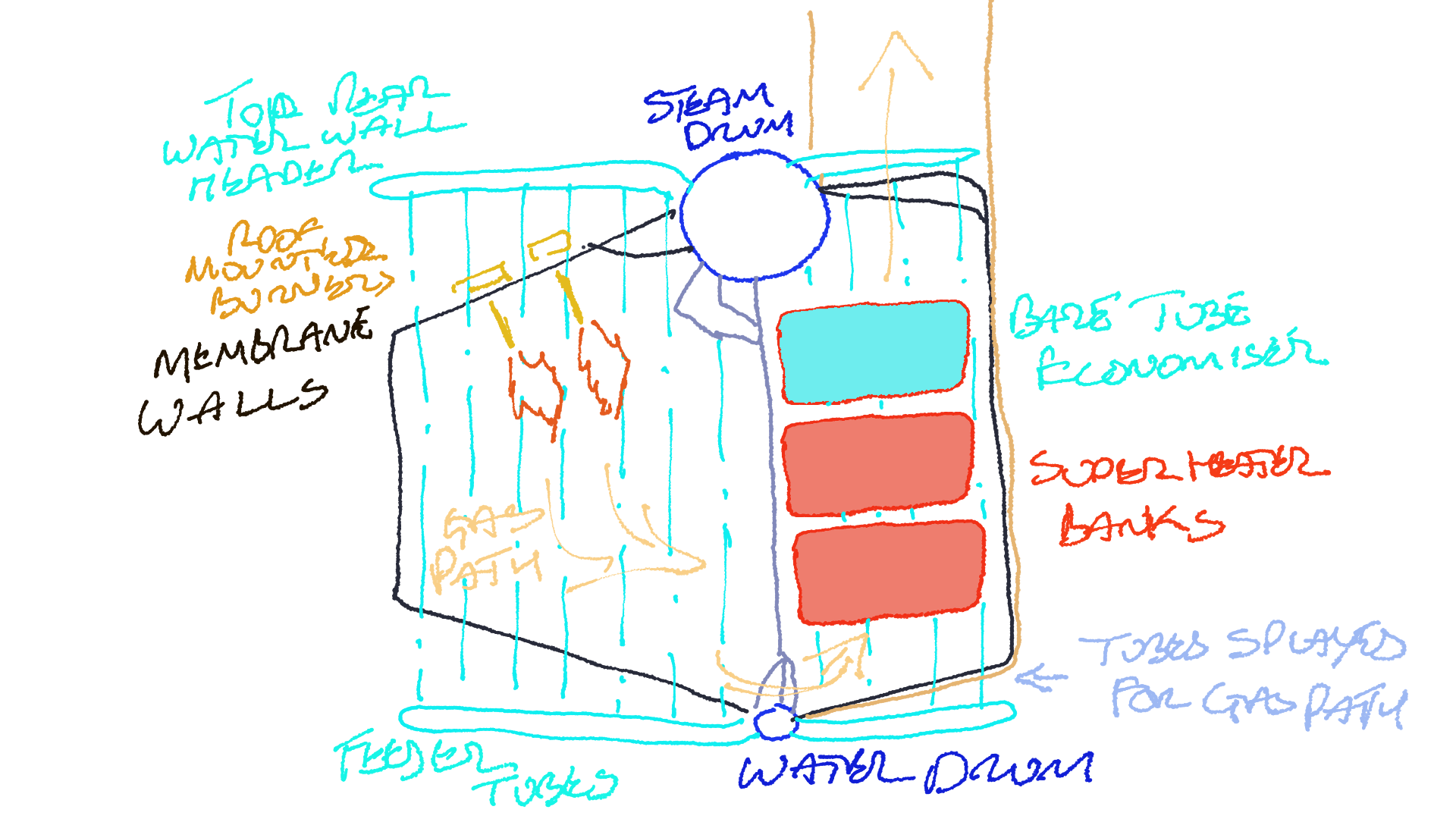
For roof fired boilers the generating bank may consist of one or two rows of close pitched tubes. For a modern radiant heat boiler, the generating bank has been omitted to allow the replacement of the water drum by a distribution header, a bare tube economiser is fitted generating 5% of the steam capacity. The generation bank is normally heated by convection rather than radiant heat.
For a set water circulation, the tube diameter is limited to a minimum as the ratio of steam to water can increase to a point where the possibility of overheating could occur due to the lower heat capacity of the steam.
The number of tubes is limited to prevent undercooling of the gas flow leading to dew point corrosion
These are larger bore tubes receiving the radiant heat of the flame and the convective heat of the hot gases. The large diameter keeps the steam/water ratio down, hence preventing overheating. There main duty is to protect the superheater from the direct radiant heat. On a modern marine radiant heat boiler, the screen wall is formed out of a membrane wall
Contains the heat of the heat of the furnace so reducing the refractory and insulation requirements.
Comes in three designs
water cooled with refractory covered studded tubes
Close pitched exposed tubes
Membrane Wall
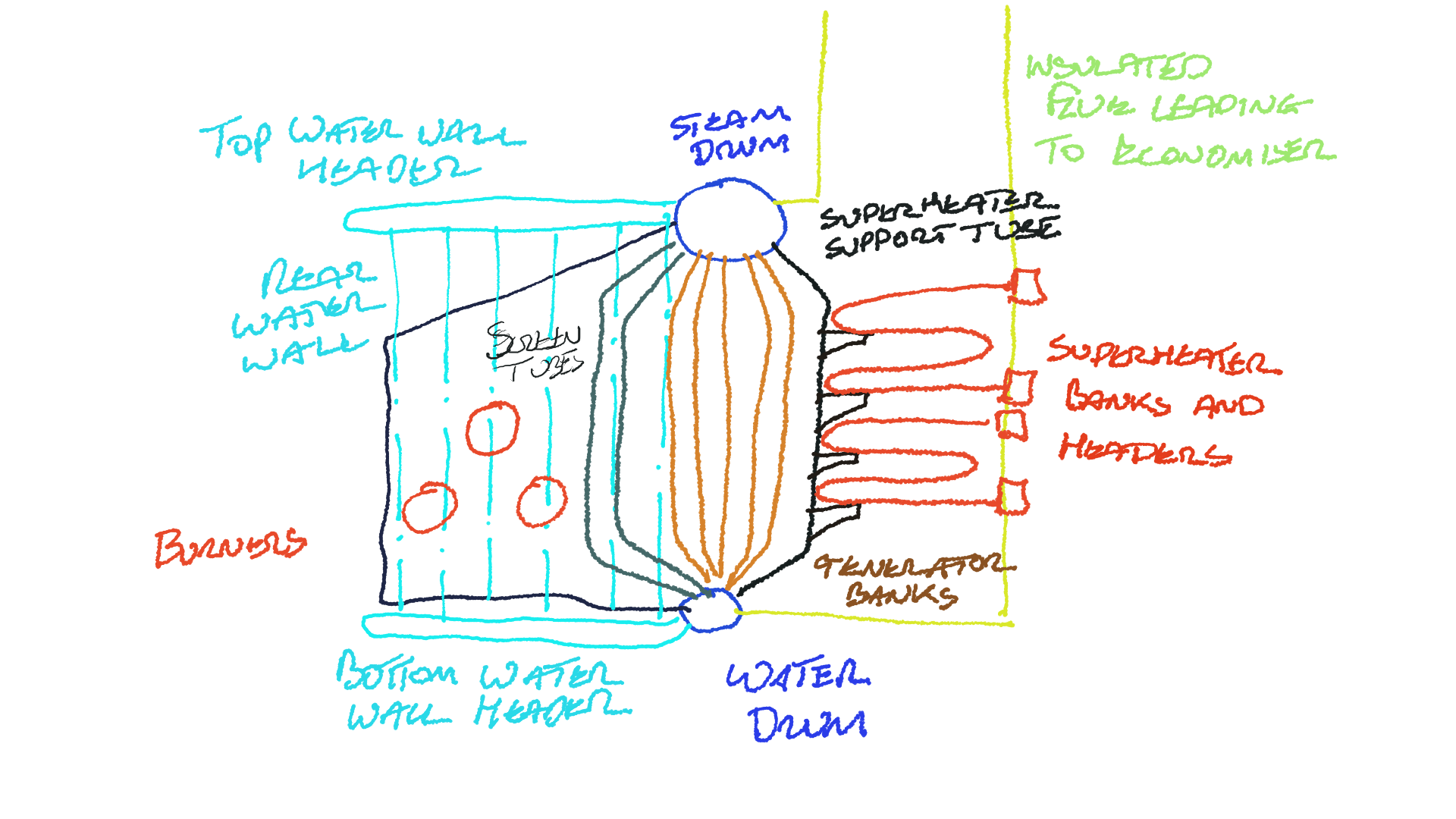
These are large diameter unheated i.e. external to the furnace, their purpose is to feed water from the steam drum to the water drum and bottom headers. They are often recognizable being outside of the gas tight casing enclosing other tubing
These return steam from the top water wall headers to the steam drum.
These are smaller diameter tubes located in the gas flow immediately after the screen tubes. Special measures must be employed during initial firing or lower steaming rates to ensure that these tubes remain adequately cooled. The steam passing through these have significantly less cooling effect (specific heat capacity) than water.
These are large diameter tubes designed to support part of the weight of the superheater bank.
Tube temperatures for the water-cooled sections is considered to be saturation temperature plus 15oC. Solid drawn mild steel is generally used.
Tube temperatures for convection superheater sections is considered to be final superheat temperatures plus 30oC. For Radiant heat a higher temperature is considered.
For Superheater tubes operating above 455oC Chrome Molybdenum alloyed steel is required.
These were originally introduced in land power stations after experience had been gained in making the lower parts of the furnace sufficiently tight to hold liquid ash. This was achieved by welding steel strips between the floor tubes. Further development resulted in completely gas tight furnace wall panels being constructed by welding together either finned tubes or normal plane tubes with steel strips in between and welded. In both methods he longitudinal welds are done by automatic processes and panels of the required size are built up in the factory ready for installation into the boiler in one piece.
Entire walls may be prefabricated
Maintenance costs, particularly of insulation are lower
Lower quality fuels may be used due to the much-reduced amount of insulation reducing problems of slagging
Simplified water washing procedures
Due to the gas tight seal, there is no corrosion of the outer casing.
A disadvantage would be that tube replacement following failure is more difficult. Also, the possibility of entire walls parting from the drum can occur during a furnace explosion.
Increased efficiency due to the longer length allowed for the flame giving more time for complete combustion. This also allows more heat to be released as radiant rather than convective cutting down the required number of screen wall generating tubes
The longer period allowed for complete combustion means that less excess air is required, this has the knock-on effect of lowering the Dew Point of the flue gasses.
Equal length flames
Better gas flow
For roof fired the heating effect from each flame is the same, for side firing it differs. To keep within the design limitations the boiler must be operated to the highest effect flame with the other two operating at reduced effect
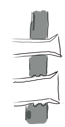
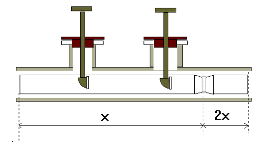
Generally associated with failure of refractory plug located beneath steam drum. It may also be related to too hard firing from cold start. Direction of the cracking indicates how it occurred
hot gasses acting on the thick section tube plate set up a temperature gradient leading to creep, plastic flow to relief thermal stress and high tensile stress on the surface at cool down. In addition, grain growth leads to the metal becoming brittle
A more severe form may lead to distortion of the entire drum in two possible directions. The thick section tube plate is exposed to the heat of the furnace and is subject to overheating. Thermal distortion takes place leading to stress. This stress is relieved by creep . When the drum cools a set distortion is in place. The distortion may occur in a radial or axial direction as shown below
Advantages over tank
Savings in weight of about 3:1 for a comparable heating surface area and saving in space for same steaming rate
Increased temperatures and pressures allowed increasing plant efficiency.
More efficient combustion shape
Water circulation better in water tube boilers
thinner tube materials allow rapid steam raising and faster heat transfer rates
reduced diameter of water tubes compared to smoke tube mean boiler content is released at a reduced rate
Thin tubes are easier to bend, expand and bell mouth
Disadvantages
Lower reserve of water means a more efficient water level control is required
Lower water volume demand stringent control on firing rates from cold starts
High quality feed required
Smaller diminution allowance for corrosion
These were the most common form of boiler design before the introduction of water tube designs.
This style of boiler still see active service were low quantities of low quality steam are required, such as for cargo and fuel tank heating when in port.
This style of boiler is relatively cheap, supplied as a packaged unit and requires less stringent feed water conditioning and level control.
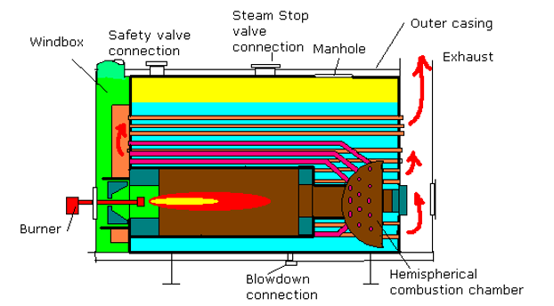
Consists of a shell wrapper plate to which is welded ( or for later designs riveted, end plates.. Pressure is naturally container in the shell plate due to is cylindrical design. The flat end plates, however, must be 'stayed' to prevent buckling and distortion.
The combustion chamber is of similar section and is also 'stayed'.
The boiler shown above is a single furnace, two pass design. Larger boilers may have multiple furnaces and have multiple passes by replacing the exhaust stack with a return chamber and fitting another bank of tubes.
The smoke tubes may be plain or threaded to act as stays. There are one stay tube for every three plain tubes approx.
To aid circulation the tubes are arranged in vertical rows to offer minimum resistance.
Fuel is combusted in the corrugated water-cooled furnace. The corrugations increase the surface area and allow a degree of flexibility to allow for expansion and contraction.
The hot gas passes to the water-cooled combustion space though to the smoke tubes. The upper portion of the combustion chamber lies close to the water level and is therefore liable to distortion due to in correct water level maintenance.
Access to the boiler is via a manhole door on the upper shell plate. In addition, a smaller door may be fitted below the furnace to allow inspection and scale/sludge removal.
This style of boiler may be fitted to the vessel as a complete unit with its own fuel and water delivery systems, control and safety equipment mounted directly on the unit. Alarms and shut downs may be are given at the local control panel which may be interfaced with ships alarms system to allow UMS operation.
The design is similar to the scotch boiler other than the combustion chamber which requires no stays. This design is a three-pass design
Although the maintenance of the water level is not so critical as with water tube designs, it should not be allowed to fall too much as overheating of furnace and combustion spaces leads to catastrophic failure due to component collapse. The content of the boiler is then expelled via the furnace door.
Similarly , although water treatment is not so critical scale must not be allowed to build up which can lead to overheating of material
Although package boilers of this design are fairly robust it should not be forgotten the potential for danger a poorly maintained unit can be.
The author carried out a supposed routine inspection
on one such unit. Opening the upper manhole revealed that the unit
had been 'wet laid' with water left at normal working level rather
than being pressed up . Severe pitting was present at and just below
the water level.
The lower manhole door beneath the furnace was
opened after draining the water. Heavy general wastage could be seen
later measured at 60 % of the shell plating with pitting on top of
this. Evidently no oxygen scavenger, such as Sodium Sulphite, had
been added before laying up.
In this condition, operation at full load would almost certainly have led to catastrophic failure.
Dual pressure boilers allow modern membrane type boilers to be used with systems where the risk of contamination is high.
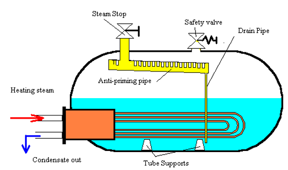
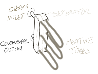
The basic design consists of a D-Type boiler design upon which is mounted a Steam/Steam generator drum. The steam generated by the main boiler heats water in the Steam/Steam generator secondary drum which produces the system steam .
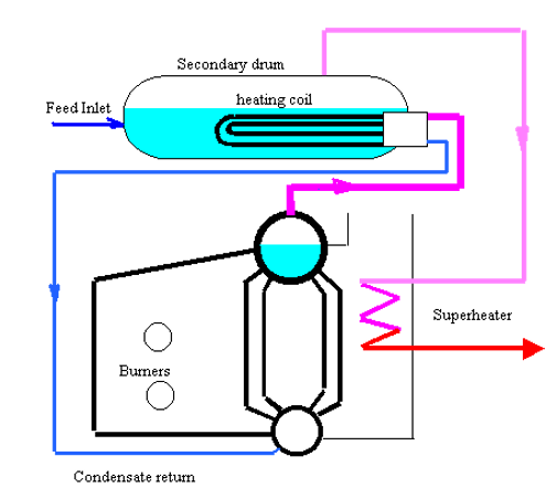
The primary drum is initially filled with high quality feed water and suitably dosed. Make up is limited to small amounts due to leakage therefore the feed pump may be of simple design. An example could be a steam or air driven reciprocating pump. The chemical treatment is simple with little requirement for addition or blowdown.
The above design shows the fitting of a superheater. These are normally only fitted where the generated steam will be required to power turbine operated machinery most typically an alternator.
The U-tube heating elements are passed through the manhole door and expanded into headers welded into the dished end of the drum. The tubes are well supported. A manhole may be fitted at the lower part of the shell allows access to the heating elements.
The drum is generally mounted integral, supports are attached to the structure of the primary boiler. The secondary drum also acts as a steam receiver for the exhaust gas boiler. Pressures are 63 bar for the primary circuit and 23.5 for the secondary.
The author has not sailed with pressures anywhere near this with this design. Primary pressures of 35bar and secondary pressures nearer 15 bar have proven sufficient even to drive an alternator. Of note is that these designs are obviously more expensive than a normal single steam drum plant even taking into account the improved efficiency. They are therefore generally associated with larger motor-powered plants with large waste heat units capable of supplying all requirements including an alternator. However, the author has sailed on this plant on a 20,000-tonne product tanker.
Where these boilers are installed in Motorships a "simmering coil" may be fitted. This is located in the primary drum and is supplied by the exhaust economiser to keep both circuits warm thereby preventing any possible damage due to lay-up.
Mountings are those typically found on any boiler with low level water alarms and low/low level shut off on both boilers. The accumulation of pressure test for the safety valves fitted to the secondary drum are calculated with the primary boiler firing at maximum rate generating maximum heating steam supply.
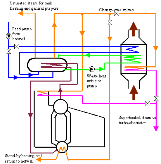
Under port conditions the main boiler is fired to provide heating steam for the secondary drum. From this steam is supplied for tank heating or to a turbo-alternator via a superheater.
When the vessel is underway the main boiler may stop firing. A waste heat circulating pump passes water from the secondary drum via the waste heat unit back to the drum. The steam produced is again available for tank heating and powering a turbo-alternator.
Crossover valves are fitted for Harbour and sea-duty conditions.
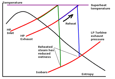
To increase plant efficiency, reheat systems are used. In this the exhaust from the HP Turbine is led back to the furnace and reheated to superheat temperatures. This allows the steam to be expanded to lower pressures in the LP turbine with reduced need for blade taper twist and other efficiency degrading designs to cope with the steam wetness.
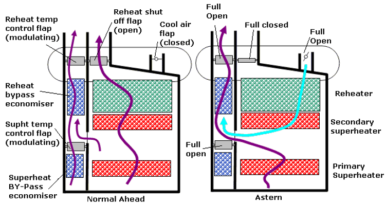
The
boiler design is of a standard roof fired radiant furnace with a gas
tight membrane water wall and single row of screen tubes. The
convection space is divided into a superheater and reheater section
and a section containing superheat and reheat temperature control
by-pass economisers. Gas dampers allow cooling air from the wind box
to pass over the reheater section during astern manouevres to prevent
overheating and thermal shocking when the plant is moved ahead.
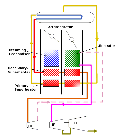
An alternate design using water drum attemperation for superheat control rather than by-pass economisers splits the convective zone into two parts
The superheaters in the reheat section ensure that gas is cooled sufficiently to prevent overheating in the reheat in the event of gas damper leakage. Provision is made to allow wind box air into the reheat space in the event of damper failure.
Advantages of MRR boiler. These are common with any radiant boiler over the convective type design
Increased plant efficiency
Improved combustion
Less excess air requirement. This has the additional advantage of reducing dew point corrosion in the uptake
Refractory limited to burner quarls and exposed section of water drum and bottom header. This allows for poor quality fuels due to reduced slagging
Furnace Gas tight
Found on steam propulsion plant and used for the production of low-pressure steam for tank heating purposes. The heating steam circuit may be separated from the main system to reduce the risk of oil contamination in the main boilers
Generally, the heating steam is supplied from the Intermediate Pressure system. Under sea conditions there is sufficient exhaust steam capacity to meet the IP system requirements. In separated duty , live HP steam may be separated, and pressure reduced as make up.
The maximum efficiency possible for a plant is given by the Carnot cycle and can be calculated using the formula
Efficiency = T1- T2/ T1
Where T1 is the maximum temperature in a cycle ( kelvin
), and T2 is the minimum temperature in a cycle.
For the steam
plant these equate to boiler outlet temperature and the exhaust
temperature of the turbine.
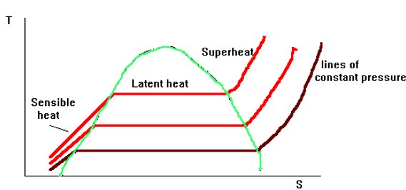
To increase final temperatures at boiler outlet conditions either; the boiler pressure can be increased, or the degree of superheat can be increased. Boiler pressure increase is ultimately limited by the scantling requirements, more importantly however, the energy stored within the steam is little increased due to the reduction in the latent heat.
Increasing the degree of Superheat not only increases the temperature but also greatly increases the heat energy stored within contained another advantage would be that the onset of condensation through the turbine would be delayed. However, this increases the specific volume which would require excessively large plants. Also there would be insufficient pressure drop for efficient expansion through the turbine. There would also be little allowance for feed heating.
There is therefore a combination of increased Pressure and Superheat to give the increased efficiency potential allied with practical design parameters.
Superheated steam, having a lower specific heat capacity then water, does not conduct heat away as efficiently as in water cooled tubes, and hence the tube metal surface temperature is higher.
This has led to the external superheat design and
parallel steam flows in an effort to keep metal temperatures within
limits
For mild steel, up to 455oC superheat is
possible; for higher temperatures, up to 560oC the use of
chrome molybdenum steels is required. The use of special alloy steels
introduces manufacturing and welding difficulties.
Superheat temperature control is a necessary
function.
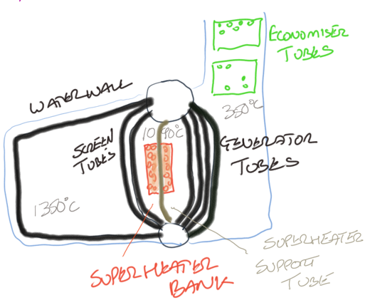
This design suffered from heavy slagging of the tubes, particularly the superheater bank, caused by the vanadium bearing ash of the increasingly poorer quality fuel blends.
This ash caused a heavy bonding slag deposit which often
bridged the gap between the tubes. This slagging attached to the hot
surfaces of the superheater support tube led to wastage and
failure.
Increasing slagging would eventually lead to blockage and
hence reduced gas path with increased gas velocities over the smaller
number of tubes, this led to overheating and failure.
Access for cleaning was limited, this and the problems outlined above led to the external superheater design
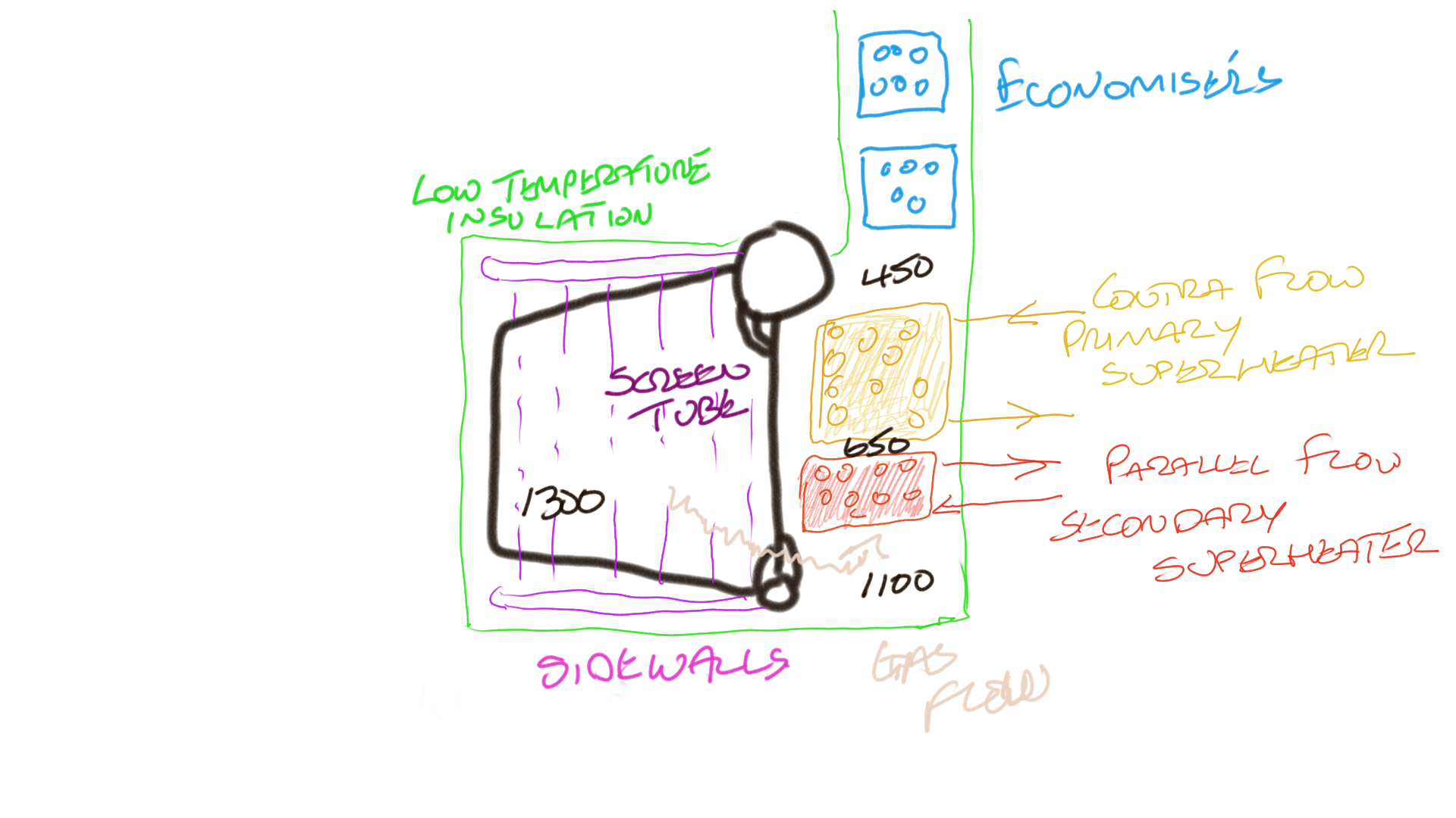
In this position the superheater was protected from the
radiant heat of the flame and with roof firing complete combustion
was ensured within the furnace space with no flame impingement, this
allied to reduced gas temperatures meant that conditions for the
superheater bank was less arduous.
The positioning of the
superheater banks allowed for easier inspection and cleaning. More
effective soot blowing could also be employed.
The positioning of the bank external meant that the surface area of the nest had to increase to give the same heating effect.
Mounting of the tubes in the athwartships direction
allowed for a simpler mounting arrangement
The secondary
superheater, mounted below the primary, was of parallel flow type
ensuring that the lower temperature attemperated steam was in the
tubes in the highest temperature zone. In modern radiant heat boilers
it is common to mount the primary superheater below that of the
secondary and use parallel flow throughout; this ensure adequate
cooling throughout.
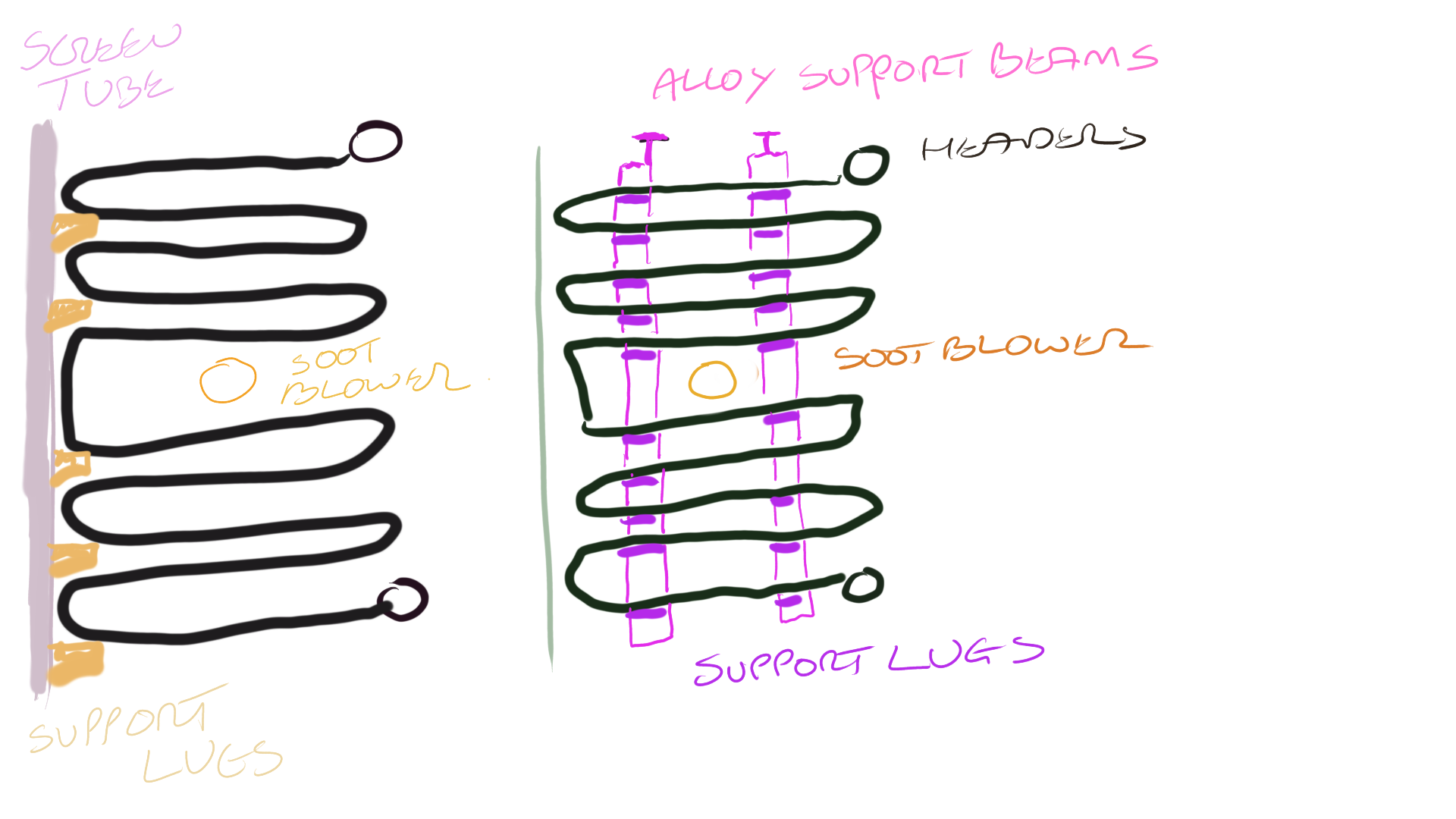
Use limited to the integral positioning fort he superheat bank, the modern method is to hang the tubes vertically, this prevents the sagging that can occur with the tubes in the horizontal.
The tubes were supported by a support plate which hung off a special increased diameter water cooler tube called the support tube. As the supports were situated in a high temperature zone they were susceptible to failure.
Division plates were welded into the headers, these allowed the steam to make many passes increasing the efficiency of the bank. Small holes were formed in these plates to allow for proper drainage, failure of these plates caused short circuiting, overheating and subsequent failures. The failure of a single tube, although possible leading to a restriction in the flow meant that the heating surface was reduced by only a small amount.
The superheater inlet and outlet flange were mounted on the same side.
In this design there are no baffles fitted inside the header, instead the steam makes a multipass over the gas by way of the many limbs or bends of each tube. The disadvantage of this system is that if a tube should fail then a significant reduction in the heating surface would occur. Simpler, more reliable support methods are possible allied to the easier access and soot blowing arrangement. This type of superheater has the advantage that the number of expanded or welded joints are reduced.
With this design the initial passes are made of Chrome Molybdenum steel. a transition piece attaches this to the mild steel passes. The inlet header is made out of mild steel and the outlet an alloy steel.
Only used in superheaters fort temperatures up to 450oC
tube ends must be cleaned and degreased and then drifted and roller
expanded into the hole, the end of the tube must be projecting by at
least 6mm. The bell mouth must have an increase of diameter of 1mm
per 25mm plus an additional 1.5mm.
It is important that the tube
enter perpendicular into the head, a seal will be assured if the
contact length is greater than 10mm, if it is not possible to enter
perpendicularly then the contact length should be increased to
13mm.
For larger diameter pipes then grooved seats are used.
Welding gives advantages over expanding in that access to the internal side of the header is not so important and so the number of handhole doors can be much reduced eliminating a source of possible leakage. Welding also generally provides a more reliable seal.
The disadvantage is that heat treatment following welding is required.
The purpose of the backing ring fitted to the conventional attachment method is to prevent the weld metal breaking through into the tube
The joints can be annealed locally by electric heat muff or torch according to manufacturers recommendations
The stub bosses can be readily blanked off externally in the event of tube failure and so do not require the access to the header internal side
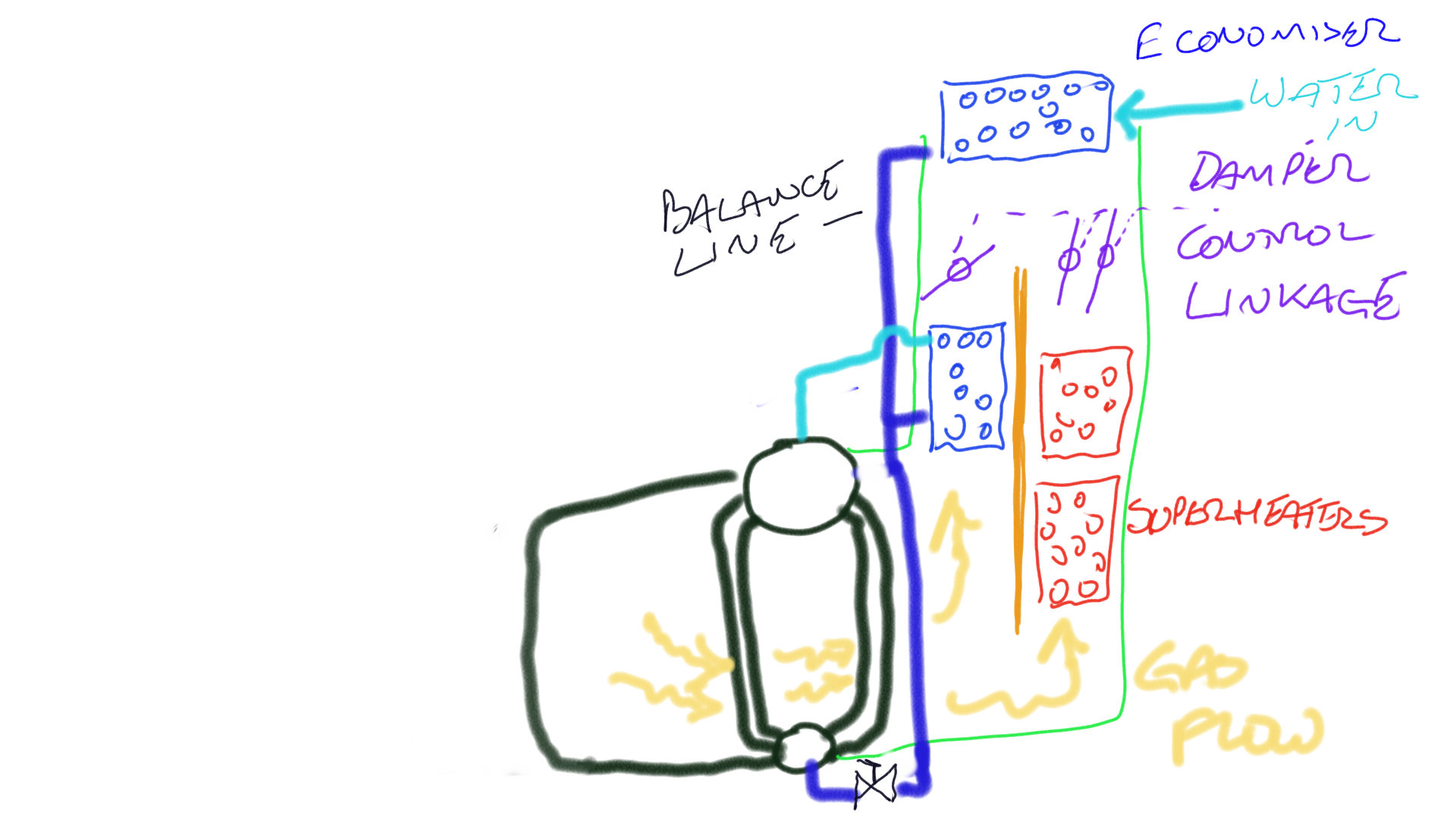
The balance line prevents any tendency for the control unit to steam under conditions of low feed flow say due to sudden load change or especially when flashing ( several of these have been burnt out due to incorrect flashing procedure)
The control unit operates the linkages via a control arm, if the superheat is too high then gases are diverted to flow over the control unit and less gas now flows over the superheat bank.
The control arms and the dampers were very susceptible to damage caused by operating in the hot gas path. Also, this control was very sensitive to excess air which can raise the superheat temperature by increasing the heat energy removed from the furnace.
This design gave a wide range of temperature control, it operated in a similar manner to the Foster Wheeler ESD II. The gas path is separated by a baffle which has flaps located above the tubes operation of which can determine the superheat temperature, as the superheater only extends across one path it is made out of 'W' rather than 'U' tubes.
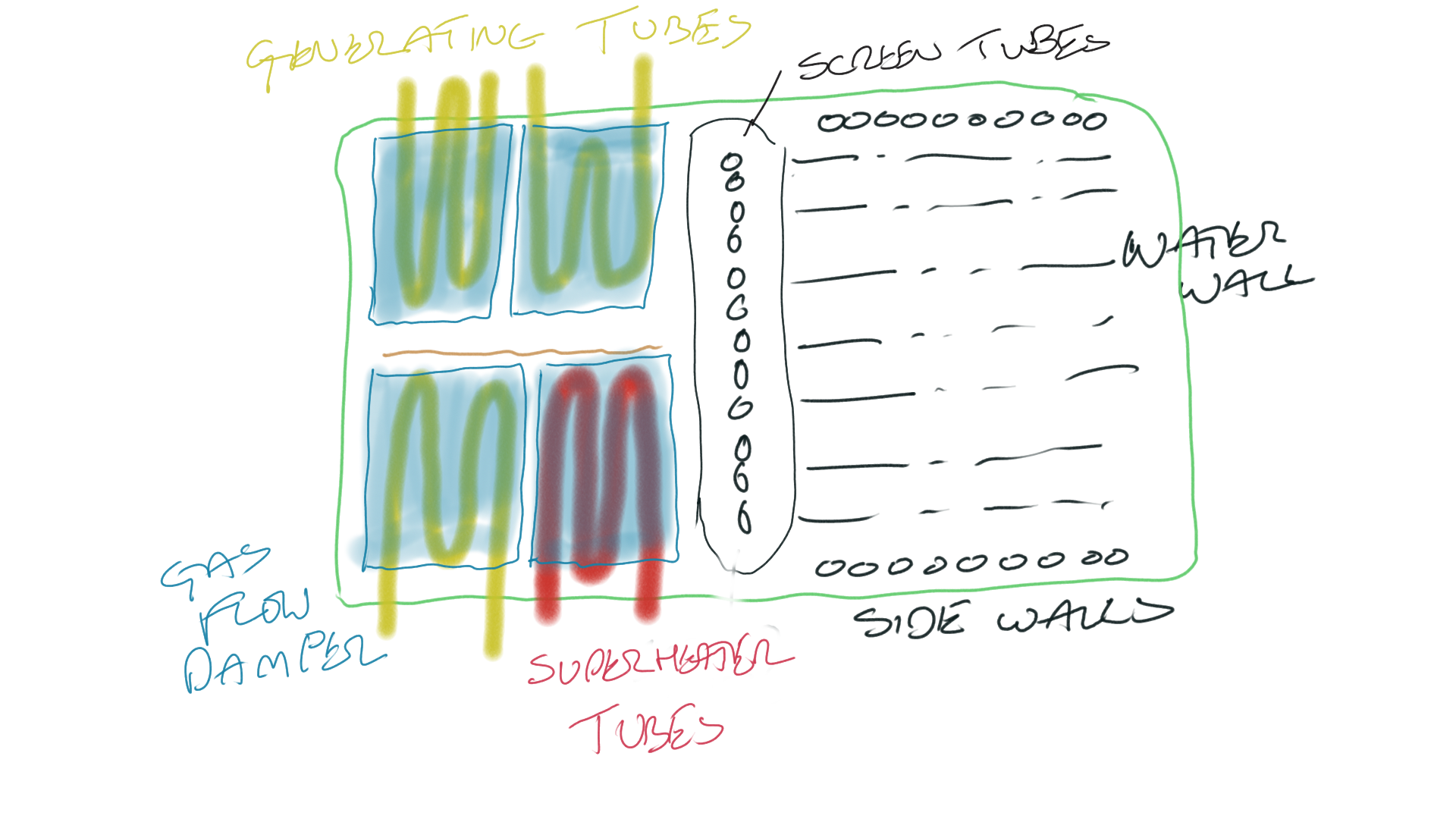
This design suffered from similar problems to the ESD II with regard to flaps and flap linkages susceptibility to corrosion.
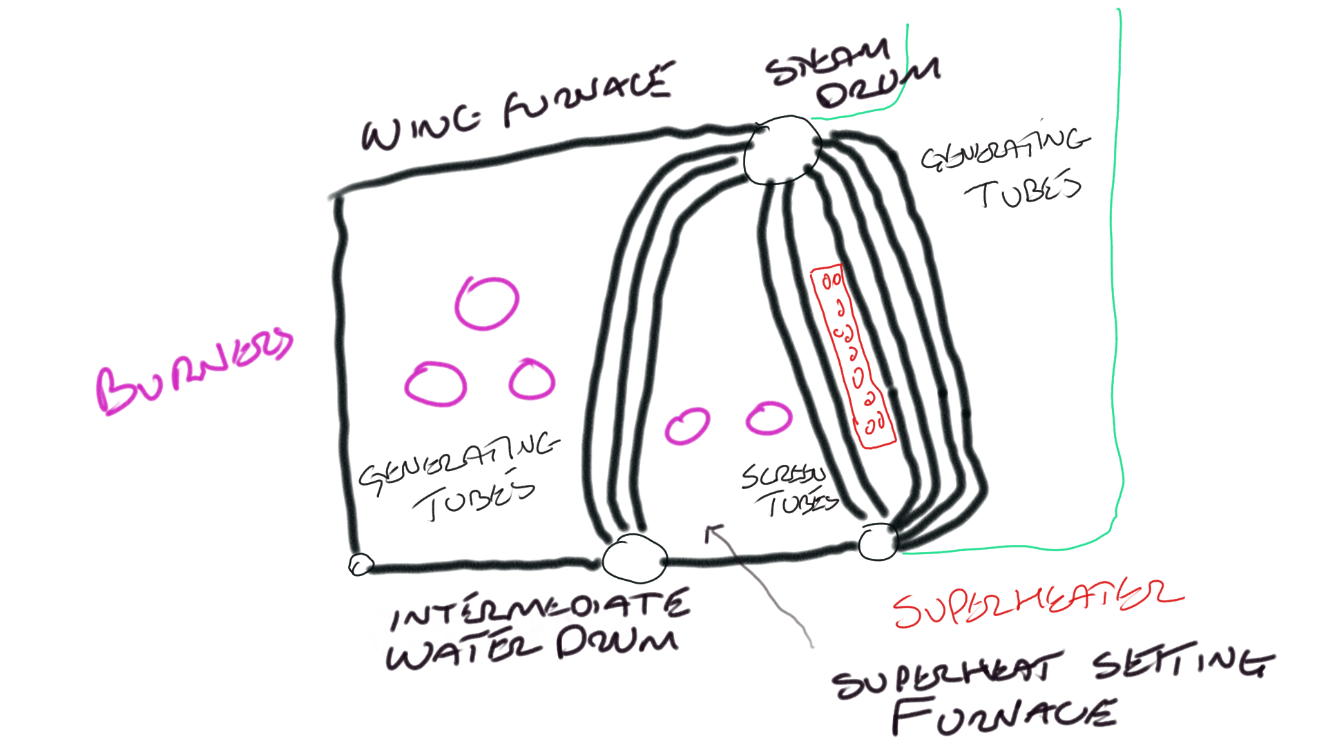
The superheat temperature was regulated by changing the position of lit burners within the boiler, shutting off burners in the main furnace and replacing them with flames in the wing furnace had the effect of reducing the superheat temperature as the gasses are cooler when the reach the superheater bank. In this way the superheat temperature could be varied by 60oC.
The advantage of this system was the superheat
temperature could be maintained over a wide variation of load. To
prevent reversal of flow in the intermediate generating bank a baffle
plate is fitted in the water drum which allows the first two rows of
the bank to be isolate from the rest and to be supplied by their own
two downcomers.
Difficulty was encountered in maintaining the
correct air/fuel ratio during differential firing of the two
furnaces.
During flashing only the wing furnace is used to give
better protection for the superheater
Air cooling effect of the double casing is lost in this arrangement so additional insulation must be fitted to ensure that the casing temperature does not exceed safe handling limits.
As air is a relatively poor cooling medium large
attemperators are required allied to increased FD fan output required
to overcome frictional resistance losses. There is an overall
increase in weight, size and initial cost which led to the system
being superseded by the regulated gas flow method and then by water
or spray cooled attemperation.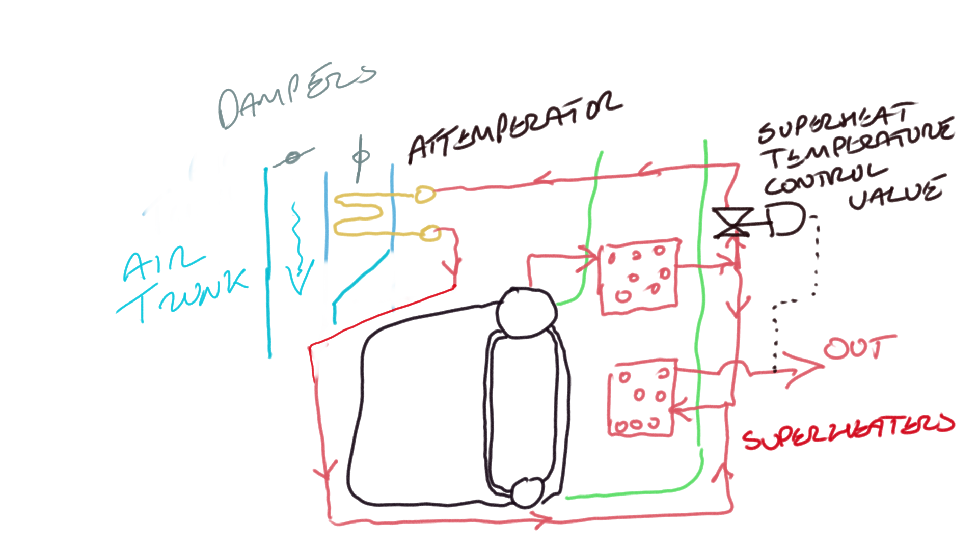
In very rare use, normally limited to tank boilers
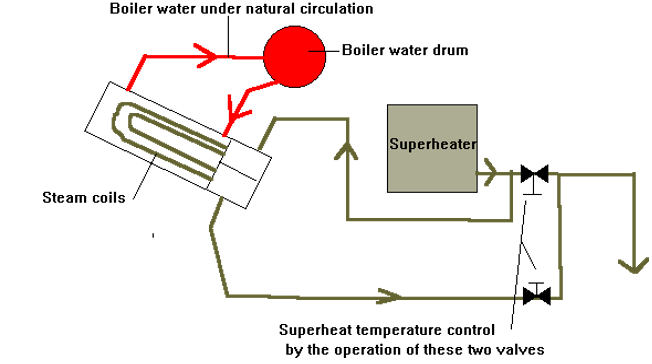
Superheat control is achieved by diverting a proportion of the steam through the simple tubular heat exchanger attemperator
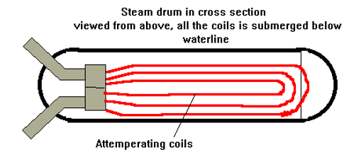
Shut off valves have to be fitted to the attemperator as in the event of tube leakage the boiler will empty into the attemperator as it is at a slightly higher pressure due to frictional losses in the superheater.
This is the most common form of attemperation in use, it consists of two spray nozzles which spray feed water into the steam as it passes from the primary to secondary superheaters. The water receives heat from the steam and thereby reduces the superheat of the steam. To prevent thermal shocking of the transfer pipe, a thin flexible inner tube is fitted.
The spray valves work in series with one reaching its maximum capacity before the second comes into use, the control system takes as its measured value both the outlet temperature and either steam or air flow (load). The spray valves are often designed to be of the air to open variety so in the event of air failure they will fail safe open
.
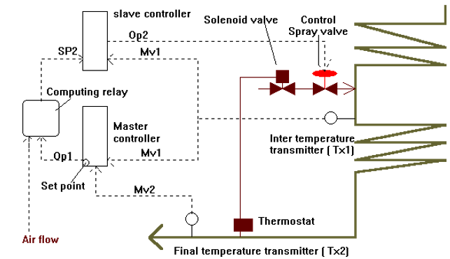
The main system components are a P+I+D Mater controller (reverse acting, hence output increases for measured values above setpoint ) in which the desired final superheat temperature is set, working in cascade is a P+I slave controller whose output controls the spray attemperator control valve.
There is a temperature transmitter on the inlet to the secondary superheater (Tx1, fitted after the spray) and a secondary superheater outlet temperature transmitter (Tx2).
Tx1 output Mv1 is fed to both the master and slave controllers, in the slave controller this forms the measured value
Tx2 output Mv2 is fed to the master controller and forms the measured value, here it is compared to the required set point entered. The output Op1 is sent to the computing relay.
Master controller Op1 = -(Desired set point -
Mv2)
(reverse acting)
In the computing relay the signal is added to the rate of change of air flow signal, as the air flow is taken from the combustion control circuit it forms a load signal. In this way the circuit has the ability to react quickly to load changes before they actually begin to effect the temperatures.
The output of the computing relay is fed to the slave controller as its set point Sp2 the set point for the slave controller now has the error of the final superheat and an amount by which the volume rate of air flow ( and hence boiler load) would tend to change the superheat contained within.
The set point Sp2 is compared in the slave controller to the output from the secondary inlet transmitter Tx1 signal Mv1.
Slave controller Output Op2 = Setpoint Sp2 - Mv1
The use of the controllers in cascade speeds up response to system changes.
Computing relay Output SP1 = OP1 + d/dt (air flow)
It is necessary to add the air flow signal as this has a direct effect on the superheat temperature. If there was a load demand increase the combustion control would increase fuel and air to the boiler, this would cause an increase in the superheat steam temperature as there would be some lag until the steam flow increased due to the increased fuel . Once the steam flow has stabilised then the increased steam flow will match the increased gas temperature and so the temperature will reduce. It can be seen then that only during the transition period when the fuel/air has increased but the steam has not that the increased spray is required, this is why the rate of change of air flow rather than volume is used in the control system.
If the measured superheater outlet temperature drops then Mv2 drops, OP1 decreases (the master controller is reverse acting), this is fed through the computing relay and so the set point Sp2 for the slave controller decreases. The set point of the slave controller has now fallen below the measured value and hence its output will decrease. This signal OP2 is fed to the spray valve which will shut in increasing the superheat temperature .
If the load on the boiler increases the output of the computing relay increases and hence the set point Sp2 increases, the output of the slave controller Op2 increases and hence the spray valve starts to open even though the increased air flow and hence gas temperature passing over the superheater is yet to be detected in the superheated steam either Tx1 or Tx2, in this way problems of process and control lags can be negated.
The output of Tx1, Mv1 is fed not only to the slave controller but also to the master controller; Its function here is to prevent the master controller from saturating and hence speeding its response under certain conditions. It does this by feeding the integral bellows via the integral restrictor in the controller rather than the more normal feedback arrangement of the output feeding the Integral bellows via the restrictor. In this way the master controller always takes account of the inter temperature.
With the normal layout in low load conditions, should Mv2 fall below the setpoint the Integral action will force the controller into saturation if the temperature fails to recover. This can happen as even with the spray valves shut there may not be enough energy in the flue gasses to heat the steam up to the required temperature in low loads.
By using the output from Tx1, Mv1 then the controller will fail to go into saturation as the integral bellows will receive a signal Mv1 rather than its falling output Op1.
Shown on the diagram is a fitting sometime used to protect the system in the event of failure of the spray control valve, this takes the form of a thermostat set so that should the temperature fall below a certain value it will operate a solenoid valve fitted before the spray control valve to shut off the feed. It can be seen that in the event of loss of superheat control , and hence with the spray valve failed open, some form, albeit very coarse , of superheat control can be maintained by use of the thermostat and solenoid valve.
There is alarms fitted to both the inlet and outlet from the secondary superheater as well as a main engine trip due to high superheat temperature. A boiler trip may be fitted for low superheater outlet temperature
These are fitted for three main reasons
To increase efficiency by recovery of heat from flue gases ( except where bled steam heaters are in use, these increase overall plant efficiency but by a different method)
Accelerate rate of combustion
Avoid effect of cold air impinging on boiler surface
As a by product air heaters also form a convenient way to warm up a standby boiler before initial firing.
However, the effects of dew point corrosion and fouling in smoke tube air heaters should be taken into account when designing the heat absorption limit. I.E. the amount of heat to be removed from the flue gas should have a limit.
For water tube boilers gas air heaters are only considered where the temperature at inlet to economiser is greater than 200oC. Due to greater heat transfer efficiency between gas/water economisers are preferred to gas/air exchangers.
At low loads all gas/air heaters should be bypassed to keep uptake temperatures as high as possible.
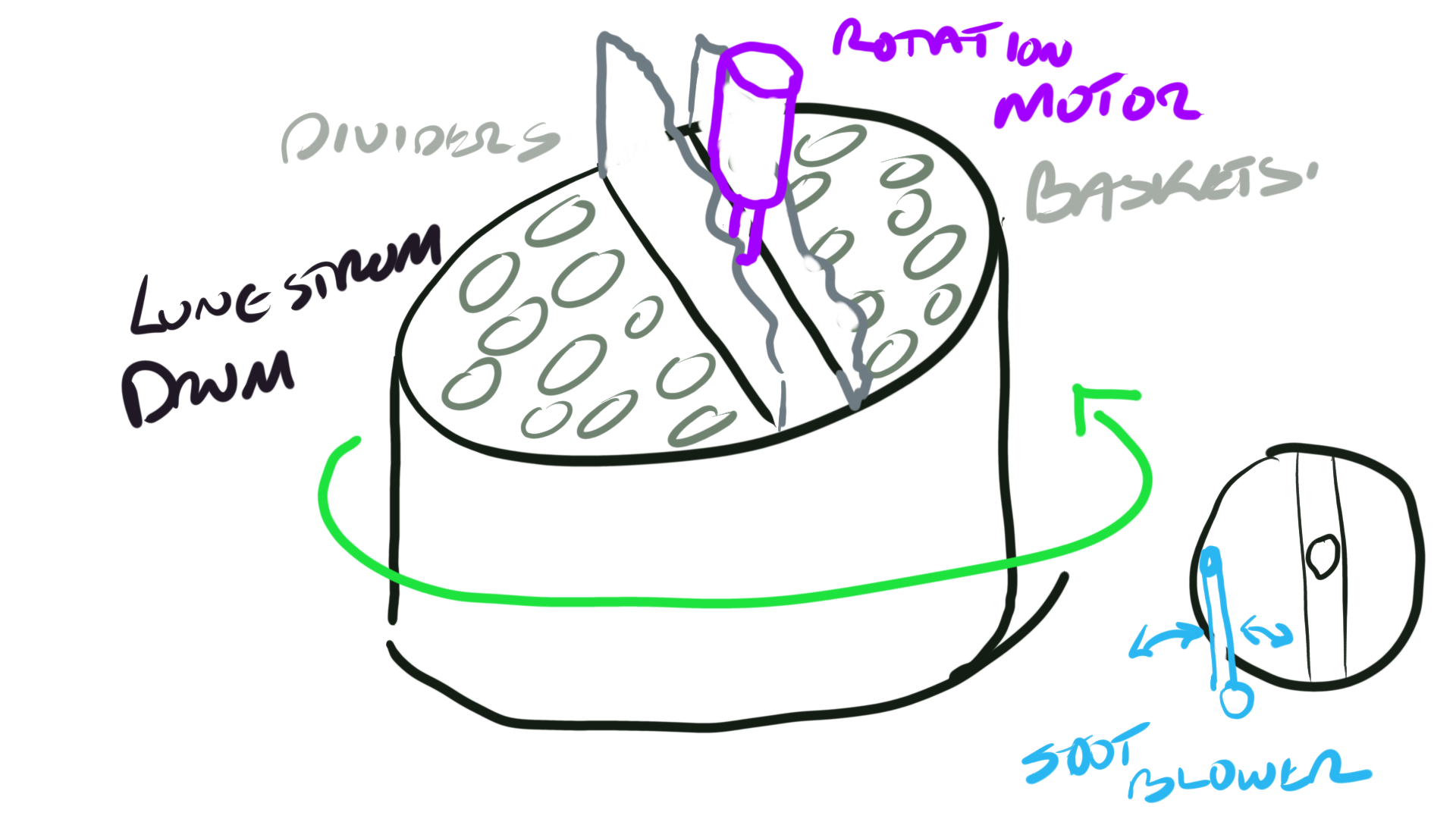
The drum contained within the cylindrical casing is formed into segments into which are placed removable ( for cleaning) baskets, consisting of vertical plates (to give minimum resistance to flow) The drum slowly rotates, about 4rev/min, driven via a flexible coupling, gear train, clutch and thrust bearing by one of two electric motors; one mounted on top the other below.
As the drum rotates a segment will enter the gas side, here it removes heat from the gas, it continues to rotate until entering the air side where it will give up its heat to the air. The heat transfer is very efficient; however, soot and corrosive deposits quickly build up in the mesh and hence an effective soot blowing method is essential. This normally takes the form of an arm , pivoted at the circumference of the drum with a single nozzle at the other end. This sweeps across the drum rather like a record arm. One of these arms are fitted top and bottom.
Gas leakage to the air side is prevented by the air being at a higher pressure and by fine radial clearance vanes fitted in the drum segments.
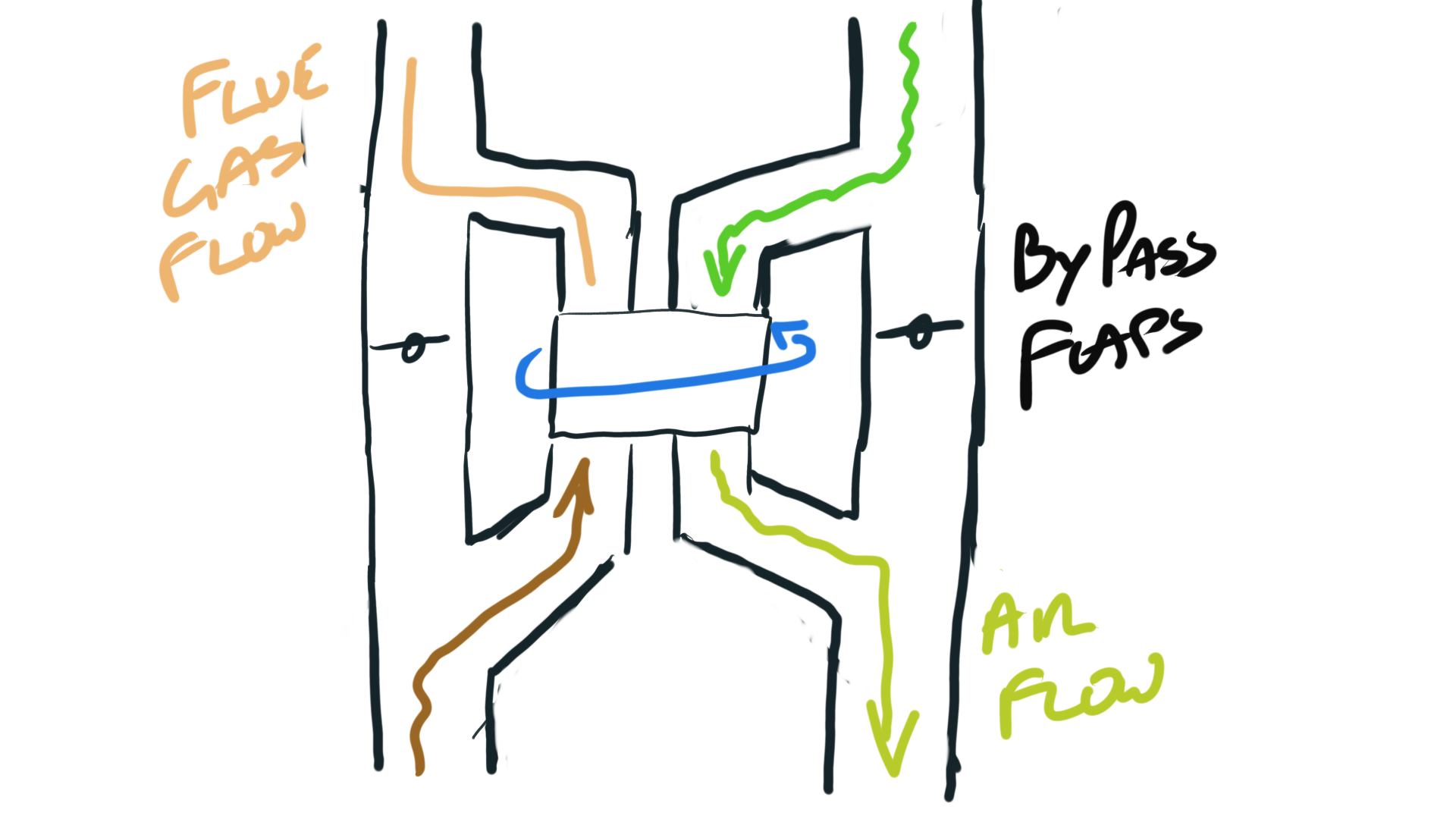
Bypass for both air and gas sides are fitted to prevent fouling with the reduced gas flow and temperature, also during manoeuvring when the possibility of different gas/air flow rates occurring leading to high metal temperatures and possible fires.
Failure by uptake fires is not uncommon with this as in most gas/air heater designs.
Author Note: I spent an unhappy day on top of one of these. After leaving the dock the soot blower wouldn’t work. As the baskets choke so does the flow to the boiler so you either bypass it or get the soot blower working. Fortunately, it was a relatively easy fix as the yard had got the blower 90degrees out of sync.
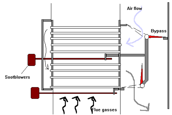
Shown above is the horizontal tube type air heater which was less susceptible to choking with soot than the vertical types sometimes found with older scotch boilers.
To aid cleaning water washing was sometimes carried out to aid the soot blowers
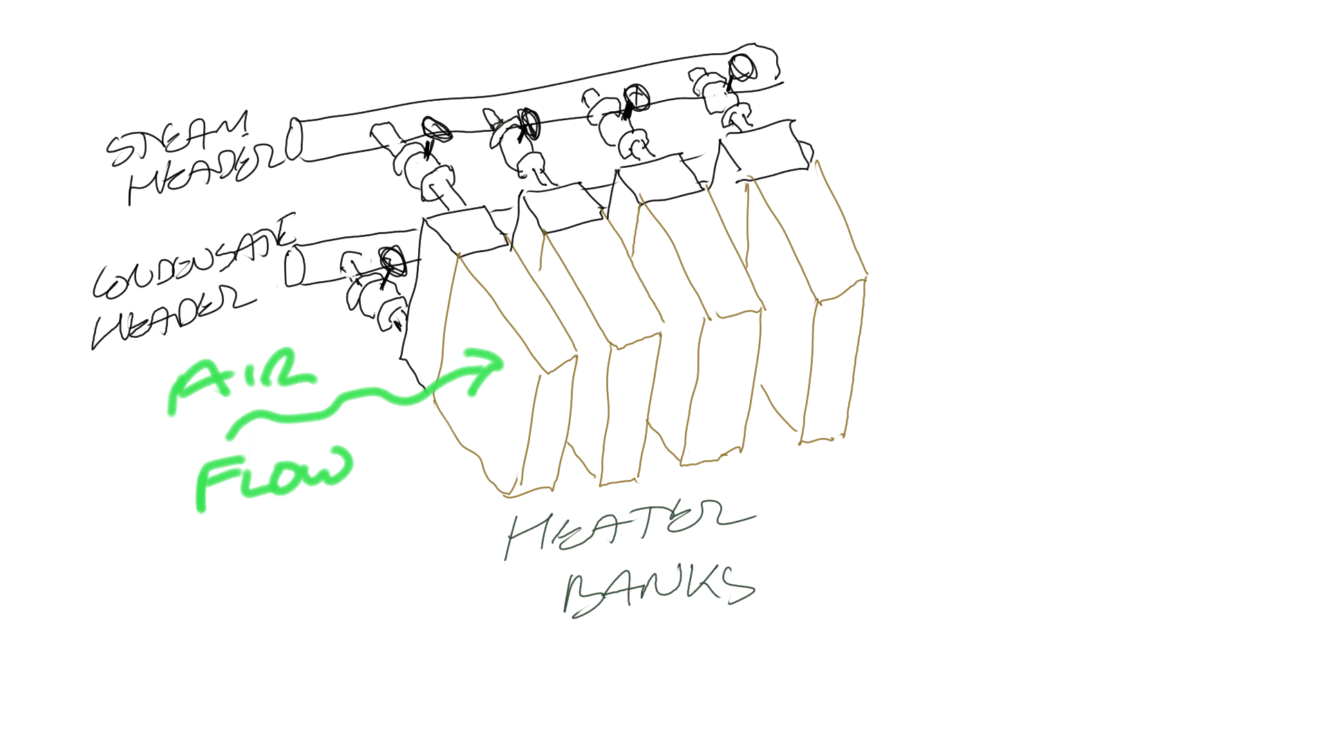
The use of individual banks and 'U' tubes allow for ease of isolation when these become perforated without large loss of heating surface. The tubes were expanded into the headers and made of cupronickel with copper fins.
Condensate headers are connected to drain traps
The heat producing constituents of the fuel are hydrogen, carbon and sulphur.
The calorific value of the combustion processes measured in mega joules for each Kg of fuel burnt
Carbon to carbon dioxide - 34
Hydrogen to water - 120.5 ( assuming the water vapor is not allowed to condense)
Sulphur to sulphur dioxide - 9.3
The main cause of heat loss is that taken away by nitrogen. Therefore, to achieve maximum efficiency the excess air should be kept to a minimum. However, there is a limit to the reduction in the excess air in that the combustion process must be fully completed within the furnace and within a finite time.
The principle combustion process is called the suspended flame. The flame front remains in the same position relative to the burner and quarl. The fuel particles pass through the flame completing their combustion process and exiting at the same rate as the fuel entering.
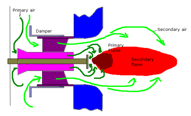
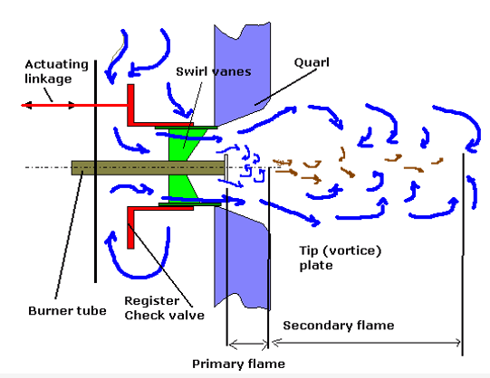
Primary Flame-To burn oil the temperature must be raised to vaporisation temperature; this cannot be done in heaters due to gassing but is done by radiant heat in the flame. The lighter hydrocarbons in the atomised spray are rapidly heated and burnt in the primary flame. The heavier fractions pass through this achieving their vaporisation temperature. The primary flame is essential to good combustion. By design the primary flame exists where it receives maximum reflected heat from the shape of the quarl. The size of the primary flame ( shown smaller than actual in drawing) just fills the quarl space. Too large and impingement leads to carbon deposits building up. Too small unheated secondary air reduces combustion efficiency. The tip plate creates vortices reducing the mixing time for the air/fuel and reduces the forward speed of the flame
Secondary Flame-Here the heavier fractions are burnt. The velocity of the air and fuel must be matched to the required flame propagation rate.
For proper combustion of fuel in the furnace and adequate supply of air must be supplied and intimately mixed with a supply of combustible material which has been presented in the correct condition.
Air- it is the purpose of the register, swirler vanes and (vortice) plates, and quarl to supply the correct quantity of air for efficient combustion suitably agitated to allow proper mixing.
The air is generally heated on larger plants to.
prevent thermal shocking
improve the combustion process
improve plant efficiency (bled steam and regenerative)
Fuel
It is the purpose of the burner to present the fuel in suitable
condition for proper combustion. Generally, this means atomising the
fuel and giving it some axial (for penetration) and angular (for
mixing) velocity. For effective atomisation the viscosity of the fuel
is critical, for fuels heavier than gas or diesel oils some degree of
heating is required. It should be noted that the temperature of the
fuel should not be allowed to raise too high as this can not only
cause problem with fuel booster pumps but also can cause flame
instability due to premature excessive gasification (is that a real
word-answers to the normal address)
The smaller the droplet size
the greater the surface areas/volume ratio is, this increases
evaporation, heating and combustion rate.
Register- supplies the correct quantity of excess air.
Too little allows incomplete combustion, smoking, soot deposits and
flame instability. Too much excess air reduces combustion efficiency
by removing heat from the furnace space, may cause 'white' smoking
and promote sulphurous deposits. In addition, too much excess air
increases the proportion of sulphur trioxide to dioxide promoting an
increase in acid corrosion attack in the upper regions.
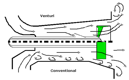
The
register and to some extent the quarl determine the shape of the
flame, short and fat for side fired boilers, long and thin for roof
fired.
Flame burning off the tip- may occur after initial ignition or after a period of high excess air. The effect of this is to move the primary flame away from the quarl thereby effecting the combustion process leading to black smoke and flame instability. Two methods of bringing the flame back are to reduce excess air and introduce a hand ignitor to ignite the fuel correctly, or to rapidly close then open the register damper.
There are six main types of burners in common use.
Pressure jet
Spill type pressure jet
Variable orifice pressure jet
Spinning cup
Steam assisted
Ultrasonic
Turndown ratio ratio of minimum to maximum flow ( roughly the square root of the ratio of maximum to minimum pressure)
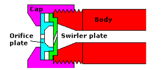
This is the simplest and oldest design of burner. Atomisation of the fuel is achieved by forcing the fuel under pressure through an orifice at the end of the burner, the pressure energy in the fuel is converted to velocity. Spin is given to the fuel prior to the orifice imparting centrifugal force on the spray of fuel causing it to atomise.
The disadvantage of this burner is its low 'Turn-Down'
ratio (in the region of 3.5). The advantage is that it does not
require any assistance other than supplying the fuel at the correct
pressure. Due to this it is still seen even on larger plant were it
is used as a first start or emergency burner.
Another disadvantage
over assisted atomisation burners is the lack of cooling from steam
or air means the burner must be removed when not in use from lit
boilers to prevent carbonising in the tube
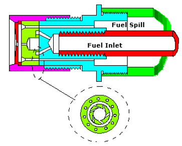
The method of atomisation is the same as for simple pressure jet type. The burner differs in that a proportion of the supplied fuel may be spilled off. This allows for increased turn down ratio
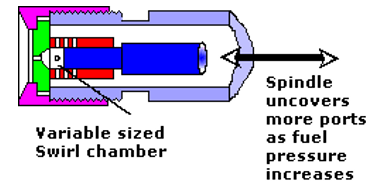
Fuel Pressure entering the burner acts against a spring-loaded piston arrangement. Increasing pressure causes the piston to pull a spindle away from the tip, this has the effect of enlarging a closed swirl chamber and uncovering ports. In this way atomisation efficiency is maintained over a greater fuel supply pressure range
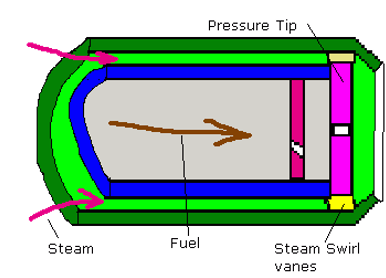
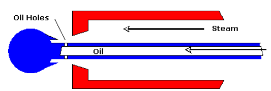
Steam assisted atomisers. This can refer to both
external and Internal steam/fuel mixing although conventionally they
refer to external mix. In these no mixing of the steam and fuel
occurs within the burner itself.
Fuel is supplied to a standard
pressure tip atomiser. Steam passes around the fuel passage and
exists through an open annulus having been given an angle of swirl to
match the fuel spray. At low fuel pressure the steam, supplied at
constant pressure throughout turndown, provides for good atomisation.
At higher fuel pressure the pressure tip provides for the
atomisation.
For first start arrangements compressed air may be used.
The two main types of internal mixing (the most common) are the 'Y' jet and the Skew jet .
Y- Jet
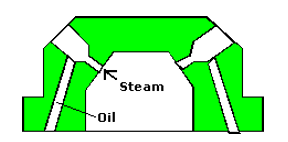
Here the steam and fuel are mixed into an emulsion and expanded in the holes before emission creating good atomisation. This design is tolerant of viscosity changes and is frugal on steam consumption and require reduced fuel pump pressures .
Skew Jet
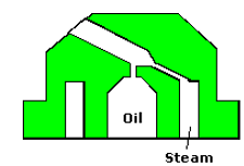
The main advantage of this design over the 'Y' jet is the reduced 'bluff' zone due to the reduced pitch diameter of the exit holes.
Matched to a venturi register, a very stable efficient flame is formed. The Fuel/Steam mix exits the nozzle in a series of conic tangents, fuel reversals inside the fuel cone allow efficient mixing with air over a wide 'Turn-Down ratio (20:1). In addition, this type of nozzle is associated with reduced atomising steam consumption (0.02Kg per Kg fuel burnt)
Manufactured by Kawasaki is said to offer the following advantages.
Wider turn down ratio with lower excess air (15 :1)
Low O2 levels
Simplified operation
Reduced acid corrosion problems
Atomisation is achieved primarily by the energy of ultrasonic waves imparted onto the fuel by the resonator tip which vibrates at a frequency of 5 MHz to 20 MHz under the influence of high-speed steam or air impinging on it. Extremely small droplet sizes result which allow for a very stable flame.
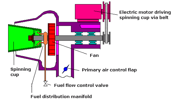
Fuel is introduced onto the inner running surface of a
highly polished fast spinning cup (3 to 7000 rpm). Under centrifugal
force this fuel forms a thin film.
Due to the conical shape of the
cup the fuel flows to the outer edge spilling into the primary
atomising air stream. The fuel is broken into small droplets and
mixed with the primary air supplied by the shaft mounted fan.
Secondary air is supplied by an external fan for larger
units.
Packaged units of this design have the air flow valve
controlled by the fuel supply pressure to the distribution manifold.
The spinning cup offers the following advantages.
Wider turn down ratio with lower excess air
Low O2 levels
No requirement for atomising air or steam
Low fuel pressure requirements to an extent that gravity flow is sufficient
stable flames achievable with very low fuel flows although maximum flows limited by size of cup. This, allied to being limited to side firing making the design more suitable for smaller installations.
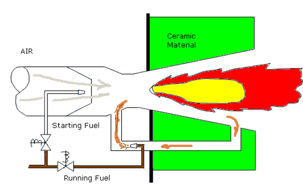
This highly efficient and clean burning method is very close to stoichiometric combustion. Under normal conditions a portion of the hot gases from the combustion process is recirculated. Fuel is introduced into the gas were it is vaporised. The resultant flame is blue with little or no smoke
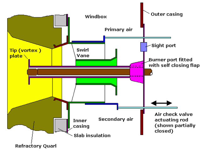
This is the name given to an assembly of vane air swirler plates etc. fitted within the boiler casing in association with each burner ,its functions is to divide air into primary and secondary streams and to direct them such as to give the correct air flow pattern.
The air must pass through the air check to enter the register . In some cases, the check can be formed by the swirl vanes themselves by rotating them about their axis, in other cases a sliding sleeve is used.
The inner primary air flows until it reaches the tip
plate ( stabiliser ) then spills over to form a series of vortices
which reduces the forward velocity of the air. This retains the
primary flame within the quarl . The outer , secondary air passes
over the swirler vanes which causes the air to rotate thus assisting
the mixing of air and fuel.
The secondary air shapes the flame,
short and fat for side fired, longer and thinner for roof fired.
A
small amount of cooling air is allowed to flow to the tip plate and
atomiser tip.
It is important that the air check forms a tight seal otherwise thermal shock can damage the quarls when the burner is not in use The front plate is usually insulated , the complexity of the air control is related to the TDR .The steam jet types have the steam providing additional energy for the mixture of air and fuel.
Furnace explosions are caused by oil vapour and air present in furnace in explosive proportions. To a lesser extent a blowback is a furnace explosion. Prevention is by purging with air.
Usually, adequate purging is provided within the combustion control however makers timings should be strictly followed .
N.B. This is particularly important with membrane wall boilers where the pressure wave is contained within a strong cell which if ruptured, has disastrous consequences.
Author Note: As first trip 4th engineer the author found himself standing next to the chief engineer as the experienced steam third engineer attempted to light a front fire D-type watertube boiler. When it failed to ignite at first attempt in a ‘faint heart never won fair lady’ moment he immediately retried without purging. The resultant furnace explosion caused the screen walls to ‘pant’. The author reacted quickly and headed to the ladder, not as quick as the Chief who-literally- climbed over the back of him leaving a footprint on his boiler suit.
Refractory is defined as a material in solid form which is capable of maintaining its shape at high temperatures- for example at furnace temperatures up to 1650oC.
To maintain the integrity of load bearing components.
To protect the boiler casing from overheating or distortion resulting in leakage of gasses into the machinery space.
To reduce heat loss and ensure acceptable cold faced temperature for operating personnel
To protect exposed parts of drum and headers which would otherwise become overheated. Some tubes are similarly protected.
Act as a heat reservoir.
To be used to form baffles for protective purposes or for directing gas flow.
Refractories must have the following:
good insulating properties.
be able to withstand high temperatures
mechanical strength to resist the forces set up by the adjacent refractory.
able to withstand vibration.
be able to withstand the cutting and abrasive action of the flame and dust
be able to expand and contract without cracking
Note: no one refractory can be used economically throughout the boiler
Acid materials- clay, silica, quartz , sandstone etc.
Neutral materials-chromite, graphite, plumbago, alumina
Alkaline or base materials- lime, magnesia, zirconia
Note that acid and alkaline refractories must be separated
Firebricks- these are made from natural clay containing alumina , silica and quartz. They are shaped into bricks and fired in a kiln
Monolithic refractories- These are supplied in the unfired state, installed in the boiler and fired in situ when the boiler is commissioned.
Mouldable refractory- This is used where direct exposure to radiant heat takes place. It must be pounded into place during installation . It is made from natural clay with added calcided fire clay which has been crushed and graded.
Plastic chrome ore- This is bonded with clay and used for studded walls. It has little strength and hence stud provides the support, and it is pounded into place. It is able to resist high temperatures
Castable refractory-This is placed over water walls and other parts of the boiler where it is protected from radiant heat . It is installed in a manner similar to concreting in building
Insulating materials- Blocks, bricks , sheets and powder are usually second line refractories. I.E. Behind the furnace refractory which is exposed to the flame. Material; asbestos millboard, magnesia , calcined magnesia block, diatomite blocks, vermiculite etc. all having very low heat conductivity.
These
are lined with plastic chrome ore
The amount of studding and the extent of tube surface covered with chrome ore is varied to suit the heat absorption rate required in the various zones of the boiler furnace.
Floor tubes may be situated beneath a 3" layer of brickwork, the tubes are embedded in crushed insulating material below which is a layer of solid insulation and then layers of asbestos millboard and magnesia.
For membrane and close pitched floors are fully cooled and no refractory is used. For front fired D- type two layers of 50 mm firebrick above the tubes and 100 mm slab insulation below. Tubes in castable insulation are covered with crushed firebricks.
Note: Before castable insulation applied ,tubes coated with bitumen to allow expansion clearance when tubes are at working temperature
In front fired boilers these need additional insulation (200 mm) made up of 125 mm moldable refractory backed by 50 mm castable or slab and 25 mm of asbestos millboard.
These have specially shaped bricks called quarls or have plastic refractory
There are two basic types.
using a hole right through the brick
Using a recess in the back of the brick.
A source of weakness is where bricks crack, bolts will
be exposed to the direct heat which leads to failure.
Adequate
expansion arrangements must be provided. For floor tubes a coating of
bitumastic is first applied before the castable refractory is
applied. When the boiler is fired the bitumastic is burnt away then a
space is left for expansion
This is one of the major items of maintenance costs in older types of boilers
This is the breaking away of layers of the brick surface. It can be caused by fluctuating temperature under flame impingement or firing a boiler too soon after water washing or brick work repair.
May also be caused by failure to close off air from register outlet causing cool air to impinge on hot refractory.
This is the softening of the bricks to a liquid state due to the prescience of vanadium or sodium ( ex sea water ) in the fuel. This acts as fluxes and lowers the melting point of the bricks which run to form a liquid pool in the furnace Eyebrows may form above quarls and attachment arrangements may become exposed Material falling to floor may critically reduce burner clearance and reduce efficiency
Flame impingement may lead to carbon penetrating refractory.
Refractories are weaker in tension than in compression or shear thus, if compression takes place due to the expansion of the brick at high temperature , if suddenly cooled cracking may occur.
Where brick securing mechanism is exposed to the heat of the furnace it may be mechanically compromised and failure to retain the brick.
At least two safety valves have to be fitted to the boiler. They may both be mounted on a common manifold with a single connection to the boiler. The safety valve size must not be less than 38mm in diameter and the area of the valve can be calculated from the following formula
C x A x P = 9.81 x H x E
where
H=
Total heating surface in m3
E = Evaporative rate in Kg
steam per m2 of heating surface per hour
P = Working
pressure of safety valves in MN/m2 absolute
A =
Aggregate area through the seating of the valves in mm2
C
= the discharge coefficient whose value depends upon the type of
valve.
C=4.8 for ordinary spring-loaded valves
C=7.2 for
high lift spring loaded valves
C= 9.6 for improved high lift
spring loaded valves
C= 19.2 for full lift safety valves
C= 30
for full bore relay operated safety valves
The safety v/v must be set at a pressure not exceeding 3% of the approved boiler working pressure. It is normal to set the superheater safety below that of the drum to ensure an adequate flow of steam for cooling purposes under fault conditions. Similarly, the superheater should be set to close last.
With all the flames in full firing the steam stop is closed, the boiler pressure must not increase by more than 10% in 7 minutes for water tube of 15 mins for tank boilers with the safety lifted. This is normally waivered for superheater boilers. Instead, calculations and previous experience are used.
The pressure drop below the lifting pressure for a safety v/v is set at 5% by regulation although it is more normal to set v/v's at 3% to prevent excessive loss of steam. For boilers with a superheater, it is important that the superheater v/v not only lifts first but closes last.
Adjustment of the blowdown may be necessary following adjustment of the popping setpoint (Increasing set point lengthens blowdown). Adjustment is achieved by altering the height of the 'adjusting guide ring' on the full lift safety valve design shown below. Over raise adjustment of this ring can lead to mal operation with the valve not fully opening
Must be set with the surveyor present except when on the
waste heat unit. A chief engineer with three years experience may
then set the safety valve but must submit information to surveyor for
issue of certificate.
Superheated steam safety valves should be
set as close to operating temperature as possible as expansion can
alter the relationships between valve trim and guide/nozzle rings
which can effect the correct operation of the valve.
Two safety valves- each set independently
Each safety valve must release entire steam flow in pressure accumulation test
Surveyor uses specially checked gauge
One valve gagged
valve initially set to approximately the correct position then steam pressure increased to set pressure
adjust valve to lift
raise and lower pressure to check
fit locks to both valves on completion
Easing gear to be checked free before setting valves. Steam should not be released as this can damage the seat.
Differences in the ordinary and high lift designs
|
Ordinary |
High Lift |
Improved high lift |
|
Winged valve |
Winged valve |
Wingless valve |
|
No waste piston |
Waste piston |
Waste piston |
|
|
No floating ring |
Floating ring |
For superheated steam the aggregate area through the seating of the valves is increased, the formula is
As = A(1 + Ts/555)
where
As = Aggregate area through the seating of the
valves in mm2 for superheated steam
A = Aggregate area
through the seating of the valves in mm2 for sat steam
Ts
= degrees of superheat in oC
As is greater than A due to the higher specific volume of superheated steam requiring more escape area.
The manifold pipe must have an area equal to at least Н of A, the exhaust must have a diameter dependent on the type of valve but up to 3 x A for a full-bore relay operated valve.
A drainpipe must be fitted to the lowest part of the valve, it should have no valve or cock and should be checked clear on regular occasions.
Materials for all parts must be non corrodible. Common materials are Bronze, Stainless steel or Monel metal, depending on the conditions of service. The valve chest is normally made of cast steel.
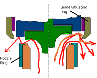
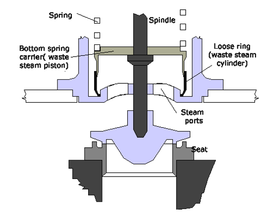
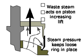
This is a modern version of the high lift safety valve
incorporating the piston and reaction force effects to improve valve
lift. In addition, the inlet pipe is tapered to give a nozzle effect
increasing the reaction on the lid.
The initial lift is produced
when the steam pressure under the disc exceeds the spring pressure.
As the valve begins to open a thin jet of steam escapes and is
deflected by a small angle on the nozzle ring. As the lift increase
the steam begins to react against the upper guide ring increasing to
'full bore' lift.
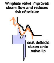
Full Bore lift is defined as that point where the area of the nozzle, rather than the lift, limits the discharge capacity of the valve. The form of the valve offers an increased area to the steam jet stream and the design allows for a piston effect of the valve trim assembly as it enters in the guide ring cylinder, both these effects increase lift and improve action of the valve .
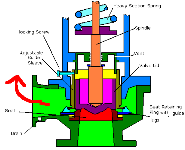
The guide sleeve is adjustable allowing alteration of the blowdown.
With boiler pressure dropping the valve begins to close.
When the lid just exits the guide sleeve there is a loss of the
reaction and piston effect, and the valve tends to snap shut cleanly.
Blowdown adjustment is achieved by altering the height of the
adjusting Guide Ring. On some designs a second adjustable ring is
mounted on the nozzle, this allows adjustment of the 'warn' or
'simmering' period and increases the popping power. Adjustment of
this ring is critical to operation, after factory setting it is
generally unnecessary and no attempt should be made to remove slight
'warn'
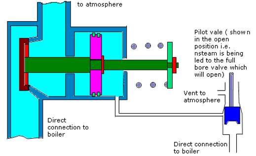
Seen fitted to large high-pressure boilers.
This design offers several advantages over simple high lift valves
Simpler design to achieve high lift
Pilot valve may be mounted on the drum and the main valve mounted on the superheater thus making the system more sensitive to load changes (over pressurisation will first be seen in the steam drum before the superheater. In addition, the pilot valve and main valve piston arrangements are subject to lower steam temperatures
Boiler pressure will assist to close the main valve rapidly leading to very small blowdown
This is fitted to safety valves to allow manual operation of the valve in an emergency.
The requirements are that there must be two independent means of reading the boiler water level. Normal practice for propulsion plant boilers are the fitting of two direct reading level gauges and a remote display readout.
Small vertical boilers may be fitted wit a series of test cocks to ascertain the level, this is deemed unsuitable for boilers above 8.2 bar and/or 1.8m in diameter.
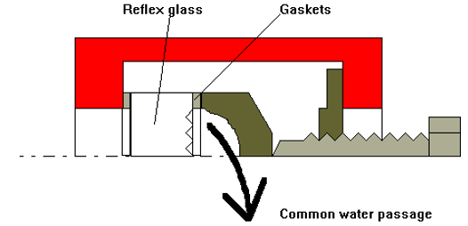
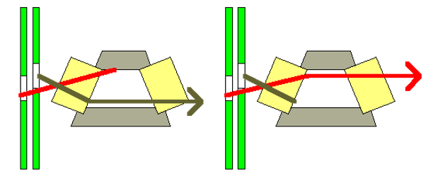
Reflex glass is used due to the fact that light falling on the glass is reflected by the steam but not by water, and so the glass appears bright where there is steam and dark where there is water.
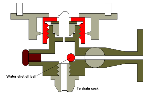
A ball is located in the water side to prevent large
quantities of water entering the engine room in the event of the
glass failing and the subsequent large expansion of the water as it
flashes off to steam. An orifice restrictor is fitted to the steam
valve.
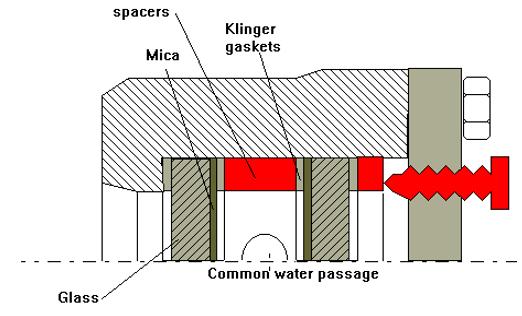
Mica is placed on the water side of the glass to protect
against erosion and chemical attack of the high temperature water.
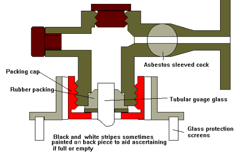
Due to the evaporation of water leaking through the cock
joints a build up of deposits can occur. This leads to restriction
and eventual blockage of the passage. If this occurs on the steam
side then the level tends to read high as the steam
condenses.
Another reason for blockage is the cock twisting, hence
the cocks are all arranged so that in their normal working positions,
i.e. steam/water open , drain shut, the handles are all pointing
downwards. Possibility of the sleeving rotating on the cock has led
to the use of ribbed asbestos sleeves which must be carefully aligned
when fitting.
For tubular gauge glasses the length of the tube is
critical and should be checked before fitting
Fitted in addition to gauges required by statute and not in place of them. The red indicator fluid does not mix with the water
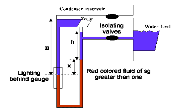
Equilibrium condition is when H= h + rx where r is the specific density of the indicator fluid.
If the water level rises h increases and x reduces. Therefore, H will be reduced, and water will flow over the weir of the condenser to maintain the level constant. If the water level were to fall h would be reduced, x increase, and H would be increased. Water therefore must be made from condensing steam in order to keep the condenser level constant.
On break out of an uptake fire the priority is to boundary cool to contain the fire and give cooling effect.
An uptake fire generally starts when the load on the boiler is reduced. This is due to the quantity of excess air being very low at high loads.
Should a fire break out then the possibility of speeding up and reducing the excess air should be considered.
The amount of feed heating should be reduced to lower the inlet feed temperature and aid with cooling parts.
Where the possibility exists of damage to the superheater, then after first relieving pressure, it should be flooded.
Where the excess air on older boilers is high even at high loads a different plan of attack must be used.
The flames should be extinguished, and the air shut off. The amount of feed heating should be reduced.
Safety should be lifted to keep a high steam flow and hence high feed flow requirements. ( the boiler is now being fired by the uptake fire )
Lifting the safeties give the added advantage of reducing the boiler pressure and hence corresponding saturation temperature of the water aiding the cooling effect
If a direct attack should be made on hot non-pressurised parts then the nozzle should be set to solid jet and aimed at the seat of the fire.
This should not be carried out on hot pressurised parts due to the risk of a steam explosion.
Dry powder is a suitable extinguishing medium.
Under certain conditions an extremely destructive fire, commonly known as a hydrogen or 'rusting' fire, may occur. Under high temperatures water will tend to disassociate to hydrogen and oxygen. The percentage amount increases with increased temperature These will recombust again liberating heat in a fire there is a danger that the use of superheated steam as an extinguishing agent (say soot blowers on an air heater fire) could in fact feed the fire and accelerate the growth. For example, the displacement which occurs about 707oC
Heat + Hot 3Fe + 12H2O Ћ 3FeO3 + 12 H2
Tackling this type of fire is very hazardous and consists mainly of boundary cooling and shutting off water and air supplies as effectively as possible. Under no circumstances should steam smothering be considered.
A typical scenario for this fire is a badly cleaned uptake igniting leading to tube failure.
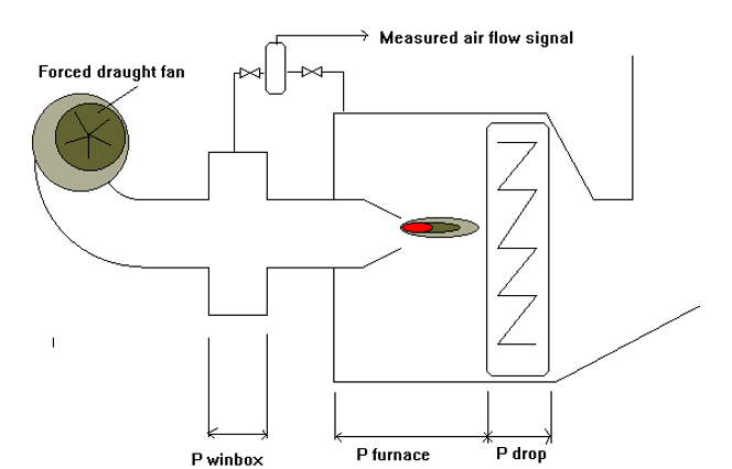
If a boiler was open ended to atmosphere then boiler panting would not occur. However, it is not, instead combustion products must flow over a whole range of items all of which contribute to a pressure drop indicated as P drop. For example, screen tubes, generating tubes, superheater tubes, economisers etc. All of these items cause a pressure drop which varies according to the combustion variations.
The system shown above is considered to be in a steady state. The windbox pressure is at a slightly higher pressure than the furnace pressure which is at a higher pressure than atmospheric.
If there was a sudden disturbance to the plant, for example, poor combustion caused by say low atomising steam pressure then combustion of the fuel would be less efficient. The pressure in the furnace will drop, the P drop increases and the mass/volume of the furnace gases increases. The actual volume of the gas has however reduced.
The furnace pressure drop will then cause increased air flow from the windbox ( after some period allowing for inertia). The density of the air remains high and Pdrop remains high.
This rush of air into the furnace aids the combustion process of the flame and also burns up any fuel products not completely combusted. This has the effect has the effect of reducing the density of the furnace atmosphere, increasing its volume, reducing Pdrop and increasing furnace pressure.
The flow of air from the windbox reduces as the pressure differential reduces. The poor combustion of the previous is re-established and the whole process is repeated.
The cycle time will depend on the aggravating process i.e. in this case the poor combustion caused by the low atomising steam pressure., the volumes of the respective chambers as well as the size of the inlet for windbox air flow and also the amount of restriction caused by the elements forming the P drop.
This example only describes one possible scenario, in reality there may be many different sources all acting together or independently to cause the panting.
Probably the most common cause of panting is an uptake fire, others may be slagging of the tube stacks or even build up of the furnace floor on front fired boilers.
The effects of panting are too causing a low frequency ( governed by volume/ P drop criteria ) oscillation of furnace spaces repeated to a lesser extent in the windbox and flue gas spaces.
For membrane boilers which are by design airtight the effect can cause heavy mechanical loading on all points especially on the drum connections, placing unwanted tensile stressing on welds. Other no less important effects are poor combustion leading to inefficient operation and choking of the tube stacks.
Modern combustion control equipment in their design inherently act to prevent panting. When the drop in furnace pressure is detected by the air flow transmitter it is sent to the P+I controller as a reduced air flow measured value. The P+I controller acts to increase the air flow hence going some way to negate the cycling problem caused by the inertia of the air.
Should a boiler start panting during its life, the condition of the internal surfaces should be inspected, and deposits removed.
Definition - various valves and fittings are required for the safe and proper working of a boiler . Those attached directly to the pressure parts of the boiler are referred to as the boiler mountings.
two safety v/v's
one steam stop
two independent feed check
two water gauge or equivalent
one pressure gauge
one salinometer valve or cock
one blowdown/scum valve
one low level fuel shut off device and alarm
SAFETY V/V-protect
the boiler from over pressurisation. DTI require at least two safety
v/v's but normally three are fitted ,two to the drum and one to the
superheater. The superheater must be set to lift first to ensure a
flow of steam through the superheater.
These must be set to a
maximum of 3% above approved boiler working pressure.
MAIN STM STOP-mounted on superheater outlet header to enable boiler to be isolated from the steam line if more than one boiler is connected. V/v must be screw down non return type to prevent back flow of steam from other boiler into one of the boilers which has sustained damage (burst tube etc) v/v may be fitted with an emergency closing device.
AUXILLIARY STOP V/V- similar to main stops but connected to the auxiliary steam line
FEED CHECK V/V'S- a SDNR v/v so that if feed p/p stops the boiler water will be prevented from blowing out the boiler. The main check is often fitted to the inlet flange of the economiser if no economiser fitted then directly connected to the boiler. The Auxiliary feed check is generally fitted directly to an inlet flange to the drum with crossovers to the main feed line. Usually fitted with extended spindles to allow remote operation which must have an indicator fitted.
WATER GUAGES- usual practice is to fit two direct reading and at least one remote for convenient reading.
PRESSURE GUAGES-fitted as required to steam drum and superheater header
SALINOMETER COCKS OR V/V'S-fitted to the water drum to allow samples to be taken. Cooling coil fitted for high pressure boilers.
BLOWDOWN COCK- used to purge the boiler of contaminants. Usually two v/v's fitted to ensure tightness . These v/v's lead to an overboard v/v.
SCUM V/V-These are fitted where possibility of oil contamination exists. They are designed to remove water and/or contaminants at or close to normal working level.
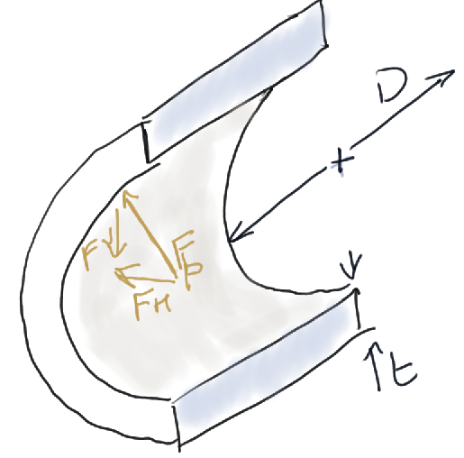
L=Length of cylinder
t= Material thickness
D=
Diameter
Fp= Force acting on cylinder due to
pressure
Fh= Resolved horizontal component of force
Equal forces act on all surfaces. If a vertical section is cut then the forces may be considered to be resisted by the longitudinal seam for the horizontal direction.
i.e. horizontal forces to left=Horizontal forces to right = resisting force in seam
Pressure x projected area = stress x C.S.A of joint
By using projected area, the horizontal component of the pressure force is automatically resolved
p x dia x L = stress x 2 x t x L
(p x dia x L)/ 2 x t= Stress ( longitudinal joint)
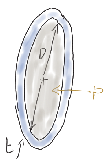
Similarly
Horizontal forces to left = Horizontal forces to right
Pressure x end plate area = Resisting force in circumferential joint
P x (pi x d2)/4 = stress x csa (circumferential joint)
= stress x pi x d x t
(p x d)/ 4 x t = stress ( longitudinal)
Hence, circumferential stress is twice that of the longitudinal stress and hence seams in the longitudinal axis must be twice as strong.