1.0 Governors
A governor, or for the purposes of this guidance a speed control governor, acts to control the speed within desired operating range.
The have
A demand signal – which can identify a fixed speed for example based on a mechanical setting; or a variable speed for example based on a electrical distribution system desired frequency.
A measured value – which may be a direct measurement of the managed engine speed, and indirect measurement of engine speed for example a generator frequency, or an indirect measurement of the effect of the engine speed as found in mechanical governors.
An output signal – commonly acting on the engine propulsive medium, for example steam supply valves or fuel rump control rack.
2.0 Mechanical governors
These fall into the oldest class of governors whose history goes back to the invention of the steam engine.
2.1 Advantages and disadvantages of mechanical Governors
2.1.1 Advantages
Simplicity and robustness - Mechanical governors, in comparison to hydraulic and electronic types, are of relatively simple, robust design able to operate with high reliability. This simplicity lends itself to applications where precise control is not a significant advantage
Maintenance – although typically requiring more maintenance than a hydraulic or electronic governor this maintenance tends to be of a simpler form in particular when resolving investigating and resolving fault. Maintainers need not have specialised training.
Cost - A mechanical governor performing the same function as a hydraulic governor tend to be more cost effective. With reducing cost of electronics this advantage is somewhat minimised.
2.1.2 Disadvantages
Speed control limitations - There is little ability to alter the managed speed range in particular during operations. Speed control is by droop only.
Response – response to speed change due to variation in load tends to be sluggish in part due to mechanical inertia and friction of moving parts.
Maintenance- Although simpler and requiring less specialised knowledge more routine maintenance is required when compare to hydraulic governors and significantly more when compare to electronic.
Size – Mechanical governors tend to be significantly larger than hydraulic or electronic governors. There is increased risk to operators due to exposed rotating or ejected parts.
Inefficient – mechanical governors absorb a portion of engine power increasing fuel consumption. Due to inflexibility of design optimising for most efficient operations is not possible. This function is particularly found in electronic governors
2.2 Working principle
The working principle of a governor is based on the equilibrium between the governor spring and flyweights. The selected spring and flyweight combination ensures that centrifugal force and spring force are balanced at the desired engine speed. When the speed increases, the centrifugal force of the flyweights increases as well, causing a reduction in fuel delivery through the system of levers. Conversely, when the speed decreases, the control rod adjusts to increase the fuel delivery rate and raise the speed to the desired level.
Governors are designed to automatically maintain all speeds, including idling and minimum speed. They are commonly incorporated into fuel injection pump designs. Diesel engine governors should possess certain qualities or characteristics to ensure effective operation.
2.3 Centrifugal (Watt type}
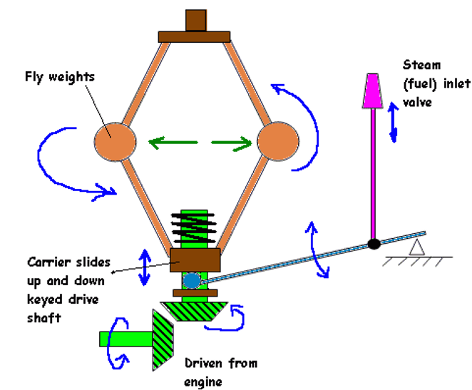
The governor assembly is directly driven from the engine. Flyweights are rotated and act to draw the slide up the drive shaft due to centrifugal force pushing them out.
2.3.1 Inertial
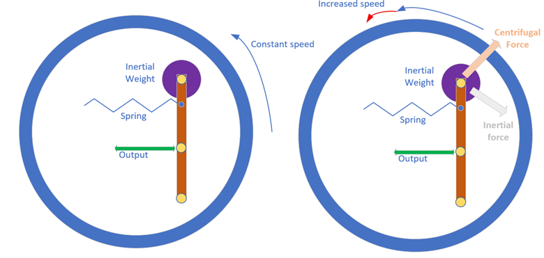
A governor arrangement rotates with the engine. With increasing speed there are two components that contribute to movement of the lever against the spring and control output. These are increasing centrifugal force and a force due to inertia.
The forces counteract in the Y-axis and so this effect is mitigated by mounting the lever in this plane. The forces are contributory in the X- axis and so the output is measured in this plane.
This inertial force acts in advance of the change of centrifugal force which makes inertial governors quicker responding to speed change compared to purely centrifugal type. The magnitude of the inertial component is dependent on rate of change and in this sense, it serves similar purpose as the derivative action on a PID controller.
3.0 Hydraulic governors
A simple mechanical governor must overcome friction in the linkages and exert a controlling force. These forces act in different directions depending upon whether the load is increasing or decreasing.The effect of this friction is to create a deadband
In hydraulic governors this effect is negated by having oil pressure act as the controlling force
This simple system has inherent stability due to the on/off nature of oil being supplied to the system control due to the control land just covering the outlet ports. Oversizing the land would create stability but at the expense of reintroducing a deadband
3.1 Servo system with feedback
An Alternative is to lead the outlet oil to a servo system. The servo piston can be either spring return or Differential
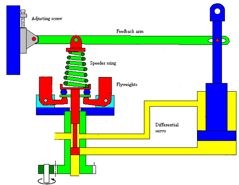
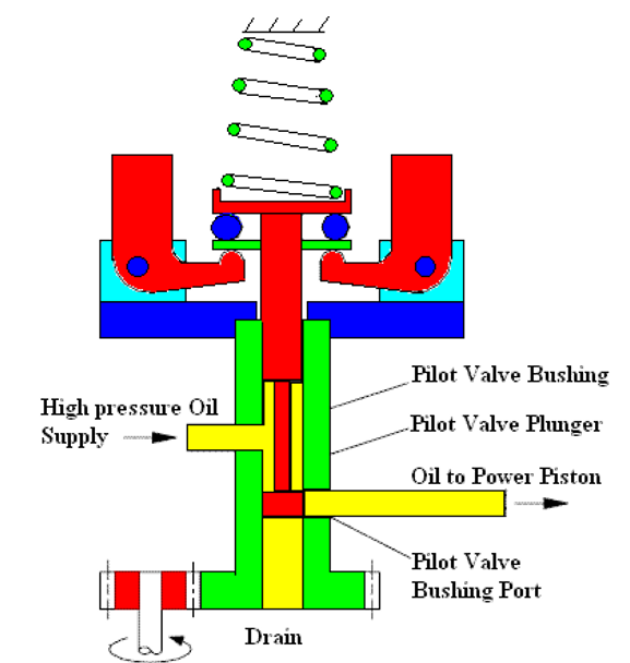
In the former case the servo is held in the decrease fuel position by spring pressure, in the latter the servo piston is pushed down by supply oil pressure. Note that the control side of the servo piston has greater areas than the supply oil side therefore when control oil is supplied it is able to lift the piston against it
Should the engine speed fall the flyweights will tend to fall towards the axis rotation due to pressure from the speeder spring overcoming the reduced centrifugal force. The pilot valve moves down and the control land allows oil to flow to the servo piston raising it. When the engine speed increases the flyweights begin to overcome the speeder spring and the pilot valve moves up covering the servo supply port
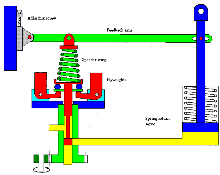
In this design Setpoint may be varied by use of an adjusting screw altering the compression of the speeder spring. In addition Feedback is given to increase stability. The term applied to this is Droop
3.1.1 Droop
Droop is defined as the reduction in speed compared to set speed over full load change x 100 as is expressed as a percentage
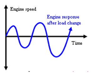
When the governor reacts to load change then inertia of the engine response can lead to overshoot in speed change which can have a cumulative effect. To prevent this a feedback system is used. In the case of the governor systems above this has the effect of modifying the speed set point .
Should the engine speed fall the flyweights will tend to fall towards the axis rotation due to pressure from the speeder spring overcoming the reduced centrifugal force. The pilot valve moves down and the control land allows oil to flow to the servo piston raising it. This increases the fuel supply to the engine but also reduces the speed set point as the feed back lever is also raised moving the connection to the speed spring upwards reducing spring pressure. The Flyweights are able to raise the pilot valve closing off the supply of oil to the servo
The engine will now run with some degree of stability. However it will not run at set speed.
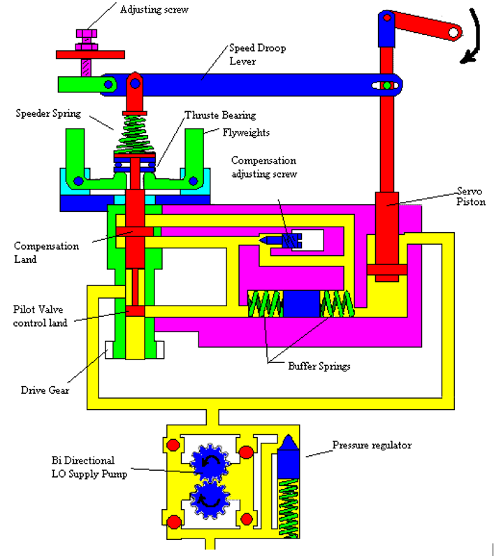
3.1.2 Compensation
This allows for the stabilising effect of droop but maintains original set point speed.
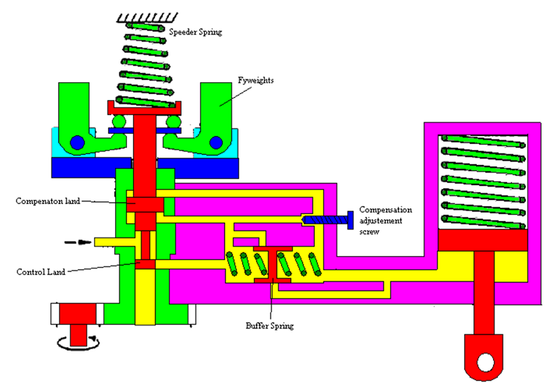
Should the engine speed fall due to the impact of increased load the control land will fall allowing supply oil pressure to pass through. As well as forcing up the servo piston via the action on the buffer spring it also acts on the underside of the compensation land were it tends to push the pilot valve up against the force of the speeder spring. The pressure differential across the compensation land bleeds off via the compensation screw as the engine returns to normal speed This is known as temporary droop
3.1.3 schematic
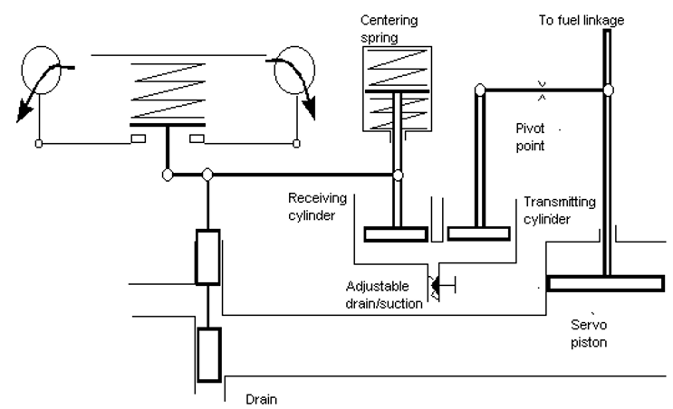
Compensation takes place to provide a further slight fuel change to return the speed to normal. The centering spring forces the receiving piston downwards and oil escapes through the adjustable valve.. This lowers that end of the floating lever until both centering springs are equally loaded and that end of the floating lever is in its original position. The pilot valve is open slightly allowing oil to the servo which gives a further slight increase in fuel. The engine speeds up, the rotating weights move out and the pilot valve is lifted until it is closed. The engine now operates with increased load, increased fuel but at the same original speed.
3.1.4 Complete assembly
4.0 Electric Governors
Electric governors have become in favour due to their compact size, rapid response and high reliability allied to low maintenance costs.
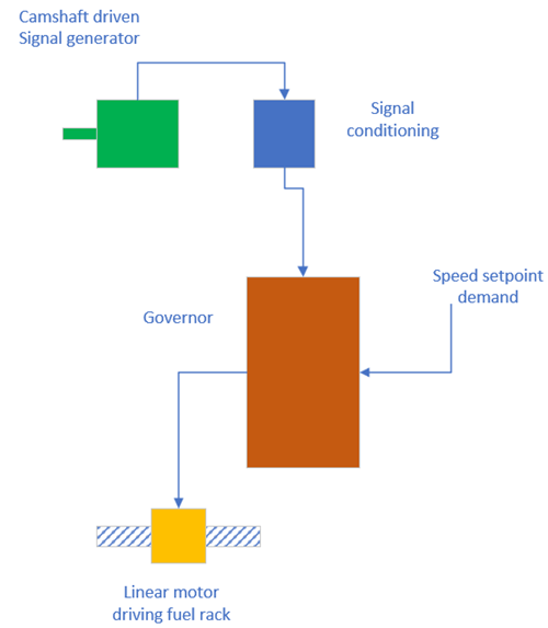
The main part of the governor is the controller and signal amplifier. This receives a D.C. signal proportional to the engine speed and compares it to a speed set signal. The difference between the measured value (engine speed) and the set value is the offset, this offset value is passed to the output circuit which produces an appropriate output signal. In this case, a signal which raises or lowers the fuel rack by an amount dependent on the degree of offset. This system is inherently stable due to the feedback layout.
For this system the engine speed is measured using an alternator driven off the camshaft- this is a common arrangement. The speed set signal is typically supplied by the bridge control arrangement via the engine management system.
An arrangement for a generator set might replace the camshaft driven alternator with a tapping off the alternator output. The frequency of the alternator output is now the measured value. In addition, a load sensing element can be introduced detecting changes in current flow. For increased current, that is an increased electrical load, the governor can act to supply increased fuel before the engine has began to slow.
5.0 Modes of operation
5.1 Droop Mode
When operating in droop mode the governor output is a product of the deviation from the desired speed. Thus with increasing load the speed of the engine will reduce by an amount dependent on the gain.
The offset may be removed by introducing integral action and speed of response to change improved by introducing derivative action.
This is a common mode of operation for engines driving electrical generators. Engines having the same droop curve are able to operate stability in parallel. Where engines have significantly differing droop curves stable parallel operation may not be possible or requires additional automation.
Operating in droop mode reduces the degree of automation and so is sometimes considered as having greater integrity. For complex power distribution systems operating in island modes, droop mode may be used in preference to isochronous.
5.2 Isochronous mode
Isochronous mode requires increased automation over droop mode and is commonly found in complex power plants running in closed bus tie where accurate frequency control is important.
Isochronous mode allows for asymmetric power distribution and is better able to provide stable power distribution for systems with large power transients, for example due to variable thruster loading.
Any fault detected causes automatic changeover to droop mode.